AutoCAD 3D Editing Basics: Tuesday Tips With Frank | AutoCAD Blog


In my last Tuesday Tip, I introduced you to some handy tools for turning your 2D shapes into 3D solids. Today, I’m going to take you just a little further with AutoCAD 3D editing and show you how easy it is to turn your extruded (or press/pulled) objects into more complex structures.

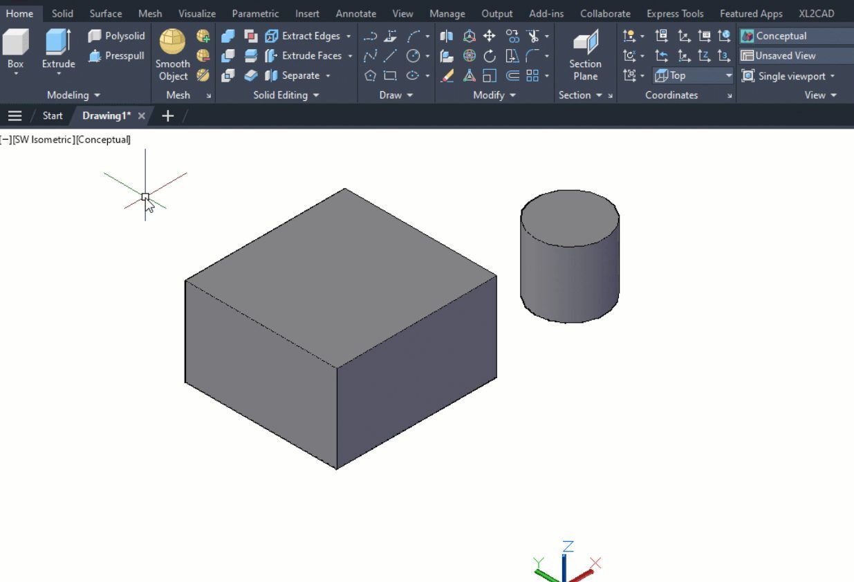
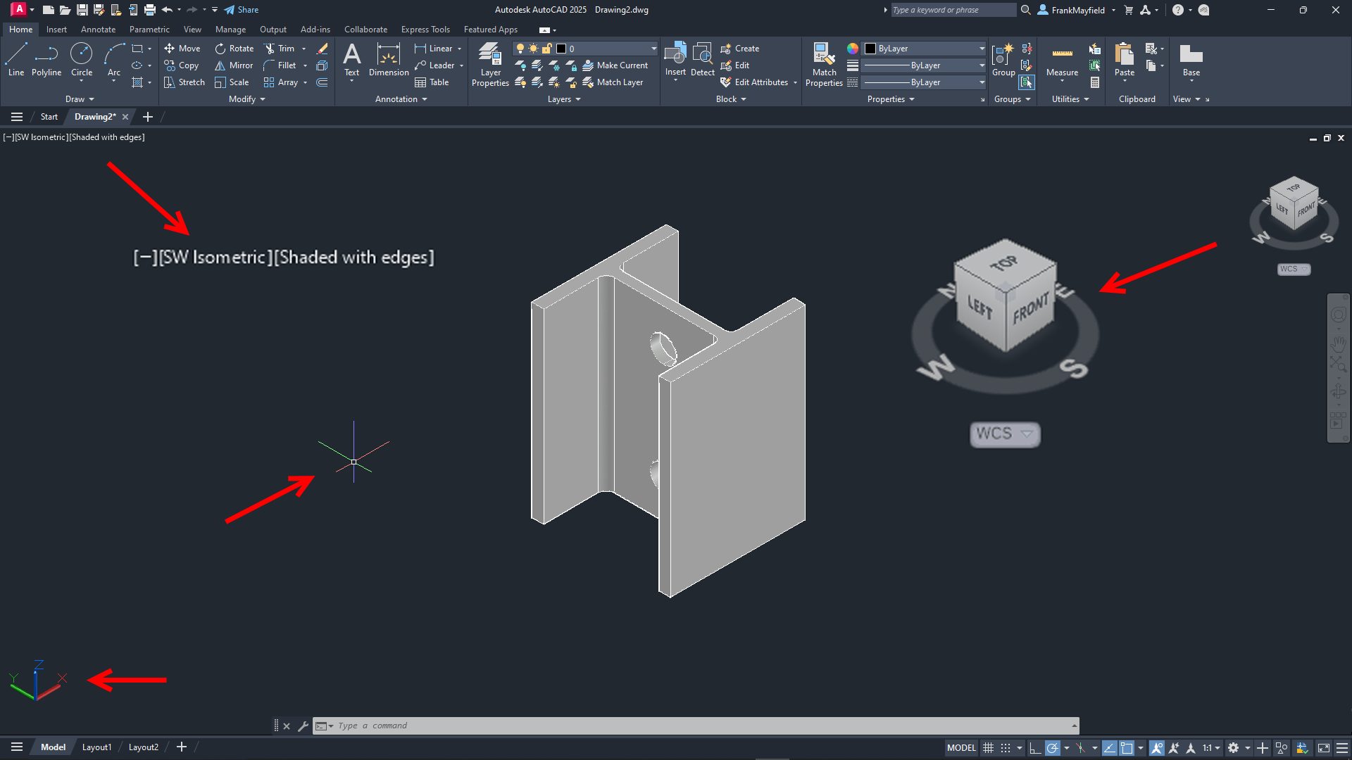
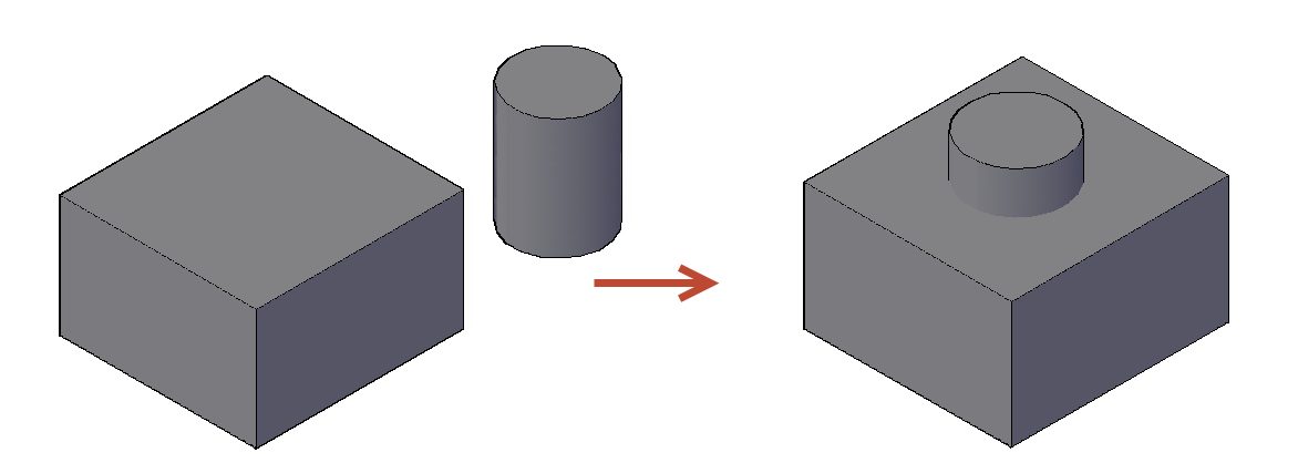
To illustrate these tools better, I will use the same simple geometry I created last time: a box and a cylinder (extruded from a 2D rectangle and a circle). However, for today’s post, I’ve moved the cylinder to the center of the box and made it a little taller.

Screenshot of cylinder and cubes in AutoCAD

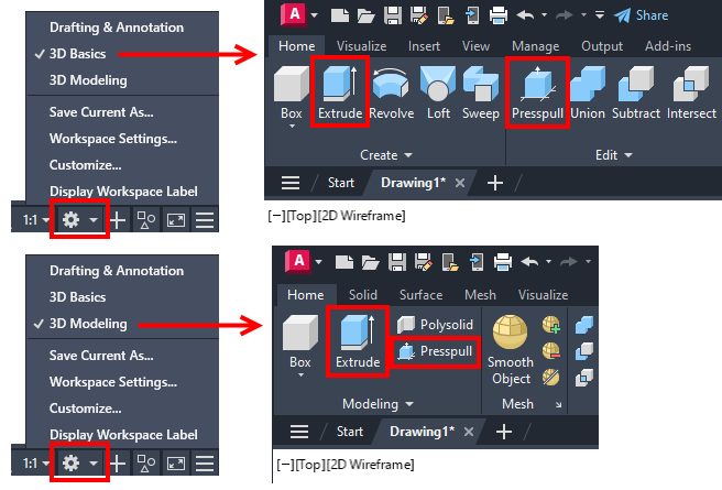
The subjects today are the 3D editing tools, Union, Subtract, and Intersect. They can be found in either the 3D Modeling workspace or the 3D Basics workspace. I’ll be demonstrating these tools via the 3D Basics workspace, as it’s a bit cleaner and easier to see the icons.

Union

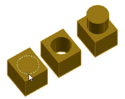
The first tool out of the box is Union. With this command, you don’t have to worry about what order you select things (more about that with the next tool). As you’ll see in the animation below, I take advantage of this by using a crossing window selection box. Quite simply, the UNION command will combine all the selected 3D solids into a single solid object. So, I no longer have a box and a cylinder, but now I have a box with some kind of a boss on top.

Please keep in mind that my examples are simply for visualization purposes and do not depict anything useful.

Animated gif of AutoCAD Union example

Subtract

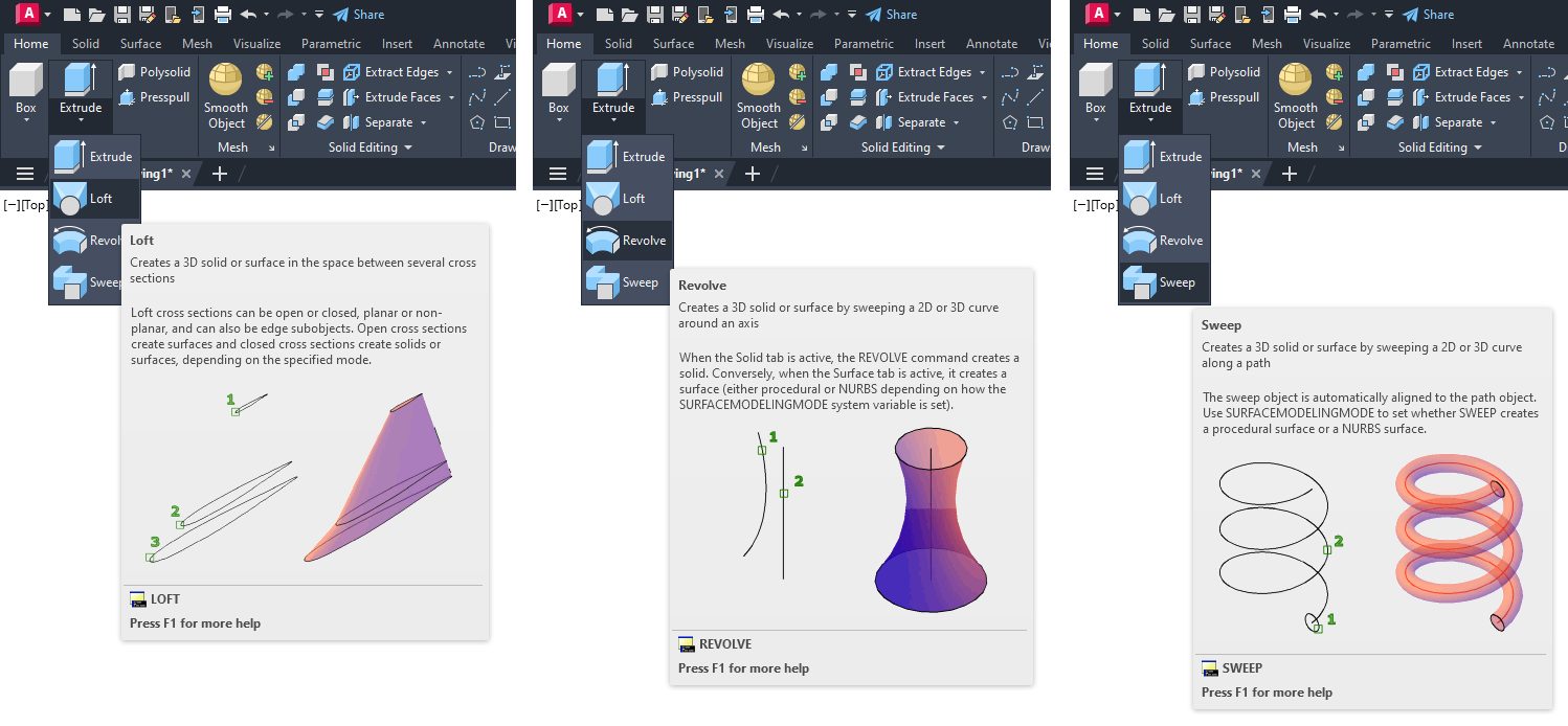
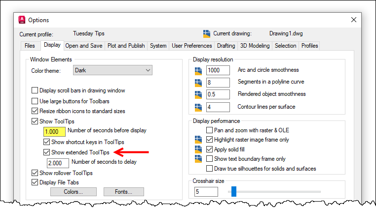
On to the second tool — the Subtract command. In this animation, you’ll notice I pause for the extended tooltip when selecting the subtract icon. This is a reminder to use these, especially in the 3D workspaces, as they give you a detailed (and sometimes animated) illustration of how the tool works.

You’ll see that its workflow is to select the object(s) you want to keep, hit enter, and then select the object(s) to subtract. In this case, I’m keeping the box and using the cylinder to subtract, thus creating a hole in the box. You may also notice that I’ve moved the Command Line into frame and used F2 to expand it into the text window. I did so because, for some reason, the prompts for what to select (the kept object vs the subtraction object) are not very clear—just something for you to keep in mind.

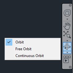
Bonus Tip: I’m using the Orbit command at the end to show the hole better. Just hold down your Shift key, press down the scroll wheel on your mouse, and just move the mouse around! It’s a fast way to visualize your 3D work.
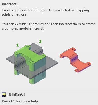
Animated gif of Subtract in AutoCAD

Intersect

The third and final tool for the day is the Intersect command. I stayed with my box and cylinder solids, but using intersect on them doesn’t do Intersect justice. It just creates a smaller cylinder. However, the extended tooltip has a terrific visual example, as shown below.

Both shapes began as 2D objects that were extruded into 3D solids. Intersect operates just as you would expect. It takes the overlapping regions of multiple 3D solids and turns the overlap into a new solid.

Screenshot of AutoCAD Intersect

Much like the Union command, you don’t have to worry about the order of your object selection. In my example animation below, I selected the box and cylinder individually, but I could have also used a crossing window as I did with Union.

Animated gif of AutoCAD Intersect

Summing Up

As you can see, these tools are not too terribly difficult to use, but they’re extremely powerful, especially when used together. Hopefully, even with my incredibly simple examples, you’ve been inspired to visualize how they can bring your seemingly complex project to fruition.

Hey, there’s nothing wrong with keeping one foot in your familiar 2D world, but don’t be afraid to put the other into 3D. Poke around some while you’re there. Expand the Ribbon Panel and see what other tools are available in the Additional Tools area. Explore both 3D workspaces. You’ll find familiar tools (3D versions of Chamfer and Fillet) and some new ones as well.

And by all means, don’t forget to hover over them to see their Extended Tooltip. It’s a terrific method for getting a feel for how a tool works before you find a need to use it.

More Tuesday Tips

Check out our whole Tuesday Tips series for ideas on how to make AutoCAD work for you.

AutoCAD 2D to 3D Made Easy: Tuesday Tips With Frank | AutoCAD Blog


Are you hesitant to make the move into AutoCAD’s 3D tools? Although it’s had 3D capabilities for decades, most people still think of AutoCAD as a 2D drafting program. What if I told you there was a way to create 3D solids so that you could better visualize your project but still draw them in your tried-and-true 2D orthographic projection?

Well, you can, and with just a couple of tools. In fact, I’m going to use a home project of mine as an example of AutoCAD 2D to 3D. Picture my house with a couple of columns on either side of the entry porch to the front door. Also, picture the bases of those columns (a square piece of a 2×10 – builders are cheap) being rotted and an eyesore due to weathering over the years. The rot even went up a few inches into the columns. Thank goodness they weren’t weight-bearing.

My job was to design a solution that would replace the bases with larger “boxes,” allowing me to remove the rotten wood at the bottom of the columns. It was time to fire up good old AutoCAD and design a solution.

I’ll simplify it for you here, but after drafting up the current as-built conditions, I realized it would be better to visualize the solution in 3D. That brings us to our subject today: Extrude and Presspull.

First Things First for AutoCAD 2D to 3D

First, you’ll need to know where your tools are. AutoCAD comes with two built-in workspaces for your 3D needs: 3D Basics and 3D Modeling. Your tools can be found in either.

Screenshot in AutoCAD of 3D Basics and 3D Modeling menus

The workflow is shown in the animated image below but let me explain it first. As I said, you’ll start in 2D. In my case, I had a rectangle (the original base) and a circle (the cross-section of the column). There is nothing very 3D about those common objects.

Once you’ve changed your workspace, you’ll want to view your work in 3D. AutoCAD makes that easy. I suggest using the View Controls pulldown menu to choose one of the pre-set Isometric views. I use SW Isometric in the example video.

Now, select the EXTRUDE command from the ribbon. Select your rectangle and hit enter to stop the selection. Pull the mouse up or down to extrude the rectangle into a 3D solid. Click to accept or type in your distance. Just like that, you’ve turned your 2D drafting skills into 3D modeling. Congratulations!

PRESSPULL works the same way in general. Both have some other options, but for my purpose today, we’re just going to get you started.

OK, in the video, I’ve extruded the rectangle and circle – the latter of which looks horrible. That’s because its default view is 2D Wireframe. You’ll want to change it to something that looks a bit more realistic. Again, we go to the View Controls and choose Conceptual. There’s no right answer here, and you have a lot of Visual Styles to select from. You’re new at this, so go through them all and find your favorite.

Video of 2D to 3D in AutoCAD

Presspull is a multi-tool. It differs from Extrude in that it allows you to create holes and 3D solid extrusions after either a press or pull.

The image below (which I lifted from the help file) shows the result of selecting the circle on top, pressing in, creating a hole, and pulling out to create an extrusion, resulting in a single object.

Example of 3D model using Presspull in AutoCAD

The other tools in the ribbon panels also let you convert 2D or 3D objects into solids, but they typically start with a 3D object, so they’re a little more complicated for the 2D drafter. They are LOFT, REVOLVE, and SWEEP.

Less important than their functionality is the makeup of the image below. I made screenshots of each of the extended Tooltips. If you have never used these or turned them off, I suggest you turn them on as a newbie to 3D. They’re a fantastic and quick resource that shows you exactly how to use each tool.

Screenshot of LOFT, REVOLVE, and SWEEP in AutoCAD

In fact, I wrote about them (and more) in my Tiptoe Through the Tooltips two-part series way back in 2018. Briefly, you can turn them on via the Display tab of the Options dialog and even set the display delay timing.

Screenshot of Options dialog box in AutoCAD

A Successful Project

After extruding my parts into 3D solids, I found that it was much easier to visualize what the final product would look like and, better yet, pass the wife’s approval. Once I was satisfied that the design would work, it took no time to go back to 2D land and design each piece, considering the construction method. I even got everything I needed out of one lone 8’ long 2×10.

Notice that I’ve said nothing about my carpentry skills. Let’s just say I’m glad I liked technical drawing as much as I did. That was certainly the right path between the two.

However, the real lesson for you is that you can stay in your 2D environment to create your designs, but now you realize just how easy it is to Extrude or Pull those closed elements into 3D solids.

Next time, I’ll discuss some of the most-used tools for editing your new solids. Stay tuned!

More Tuesday Tips

Check out our whole Tuesday Tips series for ideas on how to make AutoCAD work for you.

AutoCAD 3D Navigation and Visualization: Tuesday Tips With Frank | AutoCAD Blog


AutoCAD is often considered a 2D CAD software product, but it also has an extremely robust 3D environment. Accessing it is as easy as switching to one of the two 3D workspaces included by default. But, like moving into a new neighborhood or going to a new school, one of the first things you need to do is learn how to get around, and the 3D world of AutoCAD is no different.

You’ll be glad to know that zooming and panning in 3D work the same way as they do in 2D, so you’ve got a bit of a head start. You’ve probably already noticed some of the 3D viewing and navigation interface elements that bleed into the 2D world. They can be used there, but they’re really not very useful, so chances are you’ve ignored them. But, in 3D, they are useful, and they’re the subject of today’s post.

Please refer to the image below. The widgets in the upper left labeled as #1 are technically called Viewport Controls. The #2 item is the View Cube, and #3 is the Navigation Bar (or NavBar for short). There are some other places to find these and other tools, but today, we’re paring it down to these three, along with some keyboard and mouse methods.

Screenshot of AutoCAD Viewport Controls

Viewport Controls

Let’s start with the Viewport Control tools. There are three parts to it, and it’s an extremely efficient way to interact with your 3D model. The left widget brings up your Viewport Controls, the center one contains your View Controls, and the one on the right lets you quickly specify your Visual Style.

Screenshot of AutoCAD Viewport Controls

The following image shows the popup menu for each of the three widgets. As a 2D user, you probably equate viewport configuration to layouts. However, in the world of 3D modeling, setting up different views in Model Space can be pretty helpful. I wrote about it here on our blog as part of my Tuesday Tips series. In fact, I’m using the same model for this post as I did then (sometimes, the fine line between efficiency and laziness is a bit blurry with me.)

The View Controls (middle) is an extremely efficient way to quickly switch to a preset view of your model. Setting one takes just two mouse clicks. You can choose between all orthographic projections or from four isometric views.

The same can be said for setting a visual style. Depending on your model and workflow, you may want to change how it appears. Most of us modeling in 3D AutoCAD will have a favorite and just leave it that way. Experiment with each, and no doubt you’ll find a favorite also.

Screenshot of AutoCAD Viewports Popup Menu

Let’s set the top view of our model to be shown in the SW Isometric view and its visual style to be Shaded with Edges. When you set the view, some of the interface elements will change. I’ve either enlarged them or pointed to them in the image below. The Viewport Controls widgets will change to reflect the current setting, the View Cube will rotate to show the current view, the cursor will change into its 3D style, and the UCS icon will change.

Screenshot of 3D part with AutoCAD Viewport Controls

View Cube

Let’s now consider the View Cube. It is yet another very efficient way to change your view to a preset. Without delving too deeply into how it works (that might be a future Tuesday Tip), let’s just say that it’s a more visual, interactive way to change your viewing angle. The cube itself is made up of tiles on the faces, edges, and corners that you pick with your cursor to set that view.

You can also select one of the cardinal directions (N, S, E, W) or pick and drag your mouse along the circular compass below the cube. A home icon and a menu dropdown will also appear when you first hover over the View Cube. To change your “home view,” just right-click anywhere on the View Cube, and click “Set Current View as Home.”

AutoCAD view cube

Navigation Bar

Finally, there’s the NavBar, which shows up on the right side of the drawing editor and below the View Cube. I’m only going to talk about one of the tools within it. But it consists of – from top to bottom – the steering wheel tools (yet another full blog post of its own), pan and zoom, the Orbit tools, and, at the bottom, the Show Motion tool. Let’s focus on Orbit.

Notice there’s a little drop-down arrow just below the icon. Clicking it will allow you to set your Orbiting to a constrained orbit, a free orbit, or a continuous orbit.

Screenshot of navigation bar in AutoCAD

Again, you’re invited to try all three, and no doubt one style will become your favorite. To read about the differences between these, go to the help page on the subject.

Keyboard/Mouse Combos

With all that having been said about the interface tools, in reality, you’ll be like most users, and you’ll do all of your navigating with either just your mouse or with mouse/keyboard combos. You already probably pan and zoom with your mouse (and if you don’t… why not?).

When you’re in a 3D view, your depressed scroll wheel becomes the 3DORBIT command when used in conjunction with your Shift key. So, there’s no slowing yourself down by taking your eyes off your work to hunt down an icon. Your hands are already in place, so use them! Do you like to use Free Orbit? No problem, just add the Ctrl key, making it a Shift/Ctrl combo with the mouse wheel.

Rotating part in AutoCAD

Get Going With 3D

Hey, it’s a 3D world out there, and if you’re still using AutoCAD as just a 2D tool, there’s probably a good chance you’ll be using a 3D workspace sometime soon. Now’s a good time to get familiar with your new neighborhood and to learn how to get around efficiently.

All the methods I’ve discussed today are great to know. Try them all out and find your favorite methods. When you do get the call to work in 3D, you’ll be ahead of the game from the beginning.

More Tuesday Tips

Check out our whole Tuesday Tips series for ideas on how to make AutoCAD work for you.