How to Change Dimensions in AutoCAD: Tuesday Tips With Frank | AutoCAD Blog


In the previous Tuesday Tips, I talked about some of the more important settings to pay attention to when creating your dimension styles. In today’s post, I’ll be talking about various methods of editing existing dimensions and how to change dimensions in AutoCAD.

OK, let’s set the scene. You defined the location of the dimension incorrectly, or you need to alter its appearance or placement. By far, the easiest thing to do is to use the dimension object’s editing grips.

In the animation below, you’ll see how easy it is to select the dimension, make one of the definition points hot and place it into a new position.

After that, I hover over a dimension line grip. You’ll see a small popup menu display where you can use the dimension as the start for a continue or baseline dimension, or you can even flip the arrow! In this case, I use the grip to pull the dimension up into the room above.

Finally, hovering on the grip of the text string, will again display a popup menu with various options. Here, I choose Move with Leader to re-locate the text and draw a leader. If I had just wanted to move the text string, I would use the grip much like the prior two edits.

None of that is very hard, and it’s a very efficient way to make geometric edits to your dimensions.

Text Overrides With Special Characters

Back to Dim Style settings for a moment. A style definition will let you put the dimension text above the dimension line, or below, but not both. How can you overcome this? The answer lies in the Text Override property of the dimension object.

Below, you see a typical example of doing this. I’ve got a number of these 5’-4” dimensions and I want to add TYP below the line.

Select the dimension object, and from the Properties palette, scroll down to the Text panel. At the bottom, you’ll first see the measurement in gray, so you can’t edit it (more on that in a minute). Below that is Text override. This is the field that you’ll want to edit

There are two parts to the special characters you’re going to use. AutoCAD will interpret <> as the dimensioned measurement, the \X as a line break, and TYP as the text to place under the dimension line. By the way, the X here must be capitalized.

Text override screenshot

Please Don’t Do the Following

I just said that the Measurement property is grayed out and can’t be changed via the Properties palette. That’s great. But it can still be done. And, it’s as easy as double clicking on the text string, and typing in whatever you want.

Below, I’ve done just that. The 5’-4” measurement has changed, but instead of editing the geometry and/or making sure the definition points are accurately place, the lazy drafter just edits the text and moves on.

Here’s the worst part. You won’t know they’ve done it. It looks right, so you just assume that it is. I actually worked with a person who did this. Don’t be that person.

Measurement screenshot

Trust But Verify

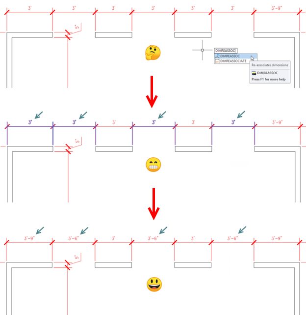
There’s an old Russian proverb that says, “Trust but verify.” To fix overridden dimension strings, type DIMREASSOC in either the Dynamic Input Box or the Command Line. You’ll be prompted to select objects. At this point, select an area, or just type in ALL since the command filters out anything that’s not a dimension. In other words, don’t take extra time to carefully select only dimensions – DIMREASSOC doesn’t care.

Note: There is also a command called DIMREASSOCIATE – fully spelled out. It does something entirely different, so please be aware.

DIMREASSOC screenshot

If there are any dimensions that have overridden text, they will be immediately highlighted for you, as shown below. Here, I find that four of the 3’ dimensions are wrong.

Incorrect dimensions screenshot

Now comes the easy part. Just hit Enter to end object selection, and Boom! All the overridden dimensions now read accurately.

There you go, dear readers. Dimension settings and editing in two parts. Next time, I’ll be presenting some of the more important things you need to pay attention to with your CAD standards, and maybe even some ways to manage them.

More Tuesday Tips

Check out our whole Tuesday Tips series for ideas on how to make AutoCAD work for you. 

Geometric Constraints in AutoCAD: Tuesday Tips With Frank | AutoCAD Blog


Remember when you were first learning to use AutoCAD? You learned about the Line command, and probably created a rectangle shape out of four line segments. Not long after, you learned about the Rectangle command and subsequently the Polyline command. You found that your rectangle is actually a closed polyline. How handy!

But it doesn’t behave like a rectangle. Grip edit a corner and end up with a weird trapezoid shape. Maybe you’ve created a slot-shaped object using the Fillet command trick that I showed you in this post. Again, you don’t want it to lose its slot shape when you edit it. But, as the animation below demonstrates, that’s exactly what happens.

What’s a drafter to do? In this case, the answer lies in Constraints. Click on the Parametric tab of the Ribbon to get started. Yes, it’s a pretty busy menu with lots of icons. If you’re like a lot of 2D drafters, you’re probably aware of it, but have also probably never used constraints for anything.

Don’t worry, this isn’t going to be a full tutorial on how to use them. AutoCAD gives you a shortcut and does the work for you. On the left side of the Geometric tab, you’ll see a large Auto Constrain icon. Using it is extremely easy. You’ll be prompted to select objects… so select the objects you want to constrain. In our example, we’ll do the slot first and the rectangle second.

But first, there are a few things you’ll want to know if this is your first experience using geometric constraints in AutoCAD.

Working with Geometric Constraints in AutoCAD

Next to the Auto Constrain icon, you’ll see all of the types of constraints you can apply. These are things like perpendicular, concentric, or parallel. When a constraint is applied to an object, an icon of the constraint type will display at the affected geometric point. You’ll want to know that you can show or hide them using the tools to the right of the geometric constraint icons.

There’s also a very handy Delete Constraints tool in the Manage tab at the far right. You’ll be prompted to select objects. Choose what you want, or if you want to affect the entire drawing, just type in All.

Why did I want to make sure you’re aware of this? Imagine getting in a drawing from an external source, and nearly all of your attempts at editing it give you weird results. What could the problem be? Well, perhaps constraints have been applied, but all of their icons have been hidden. Just click on Show All, then Delete Constraints, and select all if you don’t want them. Badda bing – problem solved. **

OK, so we’re going to be using the Auto Constrain feature on the slot. It will apply whatever constraints that it finds to your selected object(s). In this case, it uses Tangent, Parallel, and Horizontal. Now, as we see in the animation below, grip editing the shape will now retain its shape.

That was easy. Two clicks and you’re done. But there may be some situations where Auto Constrain will constrain your object too much. You can also easily manage the constraints that it will use. For our Rectangle, we want to do just that, as if you use the default set, it will be constrained so much that you can’t grip edit it all.

Your only option while in the Auto Constrain command is to access the settings box. You can do this from the pull-down menu if you have Dynamic Input turned on, or by just typing S into the Command Line. The Constraints Settings dialog can also be accessed by clicking on the little arrow icon at the corner of the Geometric panel before using Auto Constrain. If you do it this way, you’ll need to make sure to click on the AutoConstrain tab.

By default, all constraint types but Equal are checked to be used. For our rectangle, we want to apply only the Perpendicular constraint. Again, this is very easy. Just click on the Clear All button, then click on the check for Perpendicular. Close the dialog with OK, and you’re ready to go.

Select the rectangle and then enter. The perpendicular constraint icons will appear, and now when you grip-edit the corner, it retains its shape.

That’s All Folks

Geometric constraints can be extremely powerful, or incredibly annoying (especially if you don’t know they’re there). In today’s example, I’ve shown you an easy way to use them to maintain geometric shapes.

As for my story about the incoming constrained drawing? I know this because it happened to me, and more than once. Well, actually, it would happen to my users. As the CAD Manager, I’d get the call or the message, and off I’d go to debug the problem.

And a final word of warning. Do not ever, under any circumstances, use Auto Constrain on all the objects in your neighbor’s open drawing and hide their icons while your co-worker is in the break room on April Fool’s Day. It is in no way funny.

We here at Tuesday Tips HQ do not condone this behavior and disavow any responsibility.

More Tuesday Tips

Check out our whole Tuesday Tips series for ideas on how to make AutoCAD work for you. 

MOCORO and MSTRETCH Express Tools: Tuesday Tips With Frank | AutoCAD Blog


Reading this blog series, you might get the idea that I’ve used AutoCAD all of my professional life. Well, that’s close, but not entirely true. There were others, and most had some cool feature that I really liked and recall fondly.

When I left college, I immediately got a job using CAD that was required by the U.S. Navy programs we were working on. I have no clue what the software was, but I used a Tektronix 4014 during my second shift work. It was unbelievably slow, and the software itself was unremarkable, but the thing I remember most is the built-in cursor controls.

About 15 years later I took a job that required me to use a CAD software called VisionAEL. It ran on UNIX workstations, and had a really cool feature that I later reproduced with AutoLISP. When you copied something, after designating the second target point, you’d have the option to rotate it in 15* increments by using the arrow keys on your keyboard. So cool!

What’s my point? There are some great ideas that you can incorporate into your AutoCAD work. Fortunately, Autodesk has already created some of these, and they come packaged as the Express Tools in AutoCAD.

Today, I’m going to discuss a couple of favorites. One that packages multiple functions together, and another that extends the functionality of the original command. You’ll find them in the Modify panel of the Express Tools tab of the ribbon.

Screenshot of Express Tools in AutoCAD ribbon

MOCORO

The first is officially called MOCORO, short for MOve – COpy – ROtate. I alluded to it back in a post I did about Insights, but I never explained it, so here it goes. First of all, it’s slightly mis-named. It also lets you change the Basepoint and Scale, but I imagine the powers that be thought the way MOCORO rolls off the tongue is better than MOCOROBASC.

In any regard, below you can see an animation of how it works. Let’s say our task is to copy the furnishings from Arnold Green’s office number 6073 into the empty 6100 office, but aligned for the upper left corner. Your conventional move might be to copy the desk, chair, and equipment into the new office space, then rotate them, and then move them to the corner.

That’s way too much work for this lazy old drafter. Let MOCORO help you out. After each operation, you’ll get a drop-down menu (as long as you have Dynamic Input turned on) where you can choose your next function. Below, I launch MOCORO, select the objects, specify the corner, choose the rotate function next, and position it accordingly.

Each time I complete an operation, the options reappear, enabling me to choose another operation using the same selected object and basepoint. If needed, however, I can change the basepoint by selecting the Base option. Select Exit when you’re done.

MOCORO

MSTRETCH

Next up is MSTRETCH. This command enhances the stretch command by allowing you to select multiple objects to stretch. To demonstrate, I’ll use three rectangles that all need to be stretched by the same amount. We’ve all learned from our early days using AutoCAD that the Stretch command requires a crossing selection.

Short of remembering the CP selection option, stretching these three rectangles would require three stretch operations. The animation below will show you how the Stretch Multiple tool can help out.

MSTRETCH

Final Thoughts

AutoCAD has plenty of cool features sprinkled throughout the Express Tools. Way back in my first year of writing these Tuesday Tips, I wrote about finding them (and more). Don’t forget to expand the five panels in the Express Tools tab that have additional tools in their pull-down menus. Until next time!

More Tuesday Tips

Check out our whole Tuesday Tips series for ideas on how to make AutoCAD work for you. 

Managing Your CAD Standards: Tuesday Tips With Frank | AutoCAD Blog


CAD standards are the lifeblood of efficient drafting and design. Whether you work in an office of hundreds or it’s just you, CAD standards make your drawings more consistent. The CAD standards tool makes it easy to audit and even fix your standards right from within AutoCAD. Let’s walk through how to set it up, run checks, and keep your drawings on point.

Getting Started with CAD Standards

The standards checker consists of two parts: the standards file and the configuration tool. You may already have a file that houses your CAD standards, as your template probably contains all your correct layers, linetypes, and styles. Simply save that file with a DWS extension or create a new one that contains your standards. If you work in a multi-disciplined environment, you can even have multiple files, perhaps one for each discipline, such as architecture, structural, or MEP.

AutoCAD standards checker screenshot

Once you have created your standards file(s), click on the Manage tab on the ribbon and select Configure in the Standards panel. This opens the configuration dialog where you can attach your DWS file(s). You can add multiple files and prioritize them by reordering—the top file takes precedence during audits. Like an Xref, these files stay attached until you remove them, so consider adding them to your templates for maximum efficiency.

Configure AutoCAD standards screenshot

In the Plug-ins tab, select what you want to audit: Dimension Styles, Layers, Linetypes, or Text Styles. Check or uncheck as needed; the description box spells out precisely what each plug-in inspects.

AutoCAD standards plugins screenshot

Finally, you’ll want to configure what actions happen when a standards violation is found. When you click on the CAD Standards settings button, you’ll get a dialog where you can choose how, or if, you’d like to be notified of a violation, and what you want to do when a violation is found.

AutoCAD CAD standards settings screenshot

Running the CAD Standards Checker

To check your drawing vs. the standards file, click Check in the Standards panel or use the Check Standards option in the configuration dialog. The Check Standards dialog lists any issues, suggests fixes based on your DWS file, and lets you fix, ignore, or skip to the next problem.

Check standards screenshot

The audit checks both the named object, such as the layer or style name, and its properties. Choosing to fix a non-standard name will not only change the object’s name but also purge the bad name from the drawing. If the violation should be with a property of the named object, such as the color of a layer, it will simply fix the property.

If notifications are enabled, you’ll receive an alert or status bar balloon when a violation is detected, either during a check or when opening a drawing with an attached DWS file.

CAD standards notification screenshot

Another Perspective on CAD Standards

We’ve looked at this so far from the perspective of enforcing office standards. While it certainly helps with that, let’s think outside the box for a minute. Let’s assume your office hums when it comes to standards. Everything is built into your custom tools, and your company template is perfect.

One day, you get a batch of as-built drawings from the client. You are to use them in your project, but they’re not even close to your meticulously crafted CAD standards. Now what? You could assign the summer intern to scrub them all into your standards, but that would take way too much time, perhaps a whole week. Interns come cheap, not experienced.

Then you remember reading this Tuesday Tip. Donning your superhero Captain CAD cape, you make a copy of your company DWT file, rename the copy’s extension to DWS, and apply it to each as-built. You specify the settings to automatically fix non-standard properties and disable notifications, and just like that, you’re probably at least 90% done with your task.

CAD Standards Settings 2 screenshot

When you’re done, detach the DWS file, Save (of course), and delete the evidence when they’re all done (the copied DWT that became the DWS). Don’t forget to hang up your cape before you tell the boss that you took care of the conversion in a few hours, not days. Now, you’ve just set a perfect example of working smarter, not harder.

Summing It Up

Whether you’re dealing with that rogue cowboy in your office who likes to use their favorite colors or fonts, or if you’re converting another drawing to your office standards, CAD Standards maintain consistency, accuracy, efficiency, and project your company drawings’ professionalism.

The CAD Standards Manager is like a modern AI assistant that you can rely on to keep your drawings streamlined and accurate. It may not be something you use all the time, but knowing about it can help you become the office power user, or even your version of a Captain CAD Superhero (cape not included).

More Tuesday Tips

Check out our whole Tuesday Tips series for ideas on how to make AutoCAD work for you. 

Stayin’ Alive with Selection Preview in AutoCAD: Tuesday Tips With Frank | AutoCAD Blog


Shining disco balls

In the 1970s, disco music became a cultural and fashion phenomenon with clubs, disco balls, and John Travolta’s iconic dance moves in Saturday Night Fever. What does this have to do with AutoCAD you may ask? Well, have you ever dragged your mouse across a drawing, and the objects below it lit up like you’re in a disco? Rolling over text, hatches, tables, and groups may light up like it’s to a dance beat, too.

Perhaps you’re a bit like me, and while you can appreciate the visual stimulus, you’d rather just get to the point. Today, our feature is called Selection Preview, and, like many AutoCAD features, you can control how it works.

Selection Preview Settings

The first step, of course, is getting there. It starts with the Options dialog. Get there in your favorite manner – mine is to right-click anywhere in the drawing editor (with no objects selected) and select Options from the pop-up dialog.

Screenshot of options dialog box in AutoCAD

Then, in the Options dialog, click on the Select tab as shown in the image above. Finally, you’ll want to focus on the Preview settings in the bottom right.

Now that you’re where you need to be, let’s see what some of our options are.

Screenshot of preview options in AutoCAD

The first two are directly responsible for our rollover scenario, and one is part of the things I always change when I get an upgrade. We can immediately stop the disco lights when rolling over things with no command active. Uncheck the second entry. That alone will be a big change for you. Personally, I like to have only selection preview enabled when I have a command active.

You can also control what kinds of objects are lit up like a disco dance floor when they are previewed. Click on the Visual Effect Settings… button, and you’ll get the following dialog.

Screenshot of Visual Effects Settings dialog box in AutoCAD

We want to focus our attention on the right side. This is one of the more unusual dialogs in AutoCAD, as you are selecting an object type to exclude, instead of one to include. Of course, those unchecked are included, but I think you get my meaning. By default, objects on locked layers and Xrefs are excluded from preview. If you’d prefer to see them previewed, uncheck them here. Back to our scenario, this is where you can tell AutoCAD not to preview Tables, Groups, Mtext, or Hatches.

Again, you’re excluding things here, so, for example, if you never want to see Hatches preview, whether you’re in a command or not, check it here. Click OK to save and exit, and do the same for the main Options dialog.

Moving Forward

One of my favorite non-disco bands of that era led a song with the lyrics “Don’t look now, but here come the 80’s.” Not exactly a good way to make a song timeless, but hey, at least I remember it 45 years later.

By that time, though, the disco age was coming to a close, culminating in a 1979 “Disco Demolition Night” event at a Chicago White Sox home double-header, which quickly devolved into a riot of fans burning disco records.

The good news for you is that you can keep AutoCAD from looking like a disco dance floor and more like a streamlined, fast CAD program. It’s just a matter of knowing where to go and what to adjust.

When you do, those polyester suits, gold chains, and slicked back hair will stay in the disco era where they belong.

More Tuesday Tips

Check out our whole Tuesday Tips series for ideas on how to make AutoCAD work for you. 

3 Ways to Get Back! AutoCAD REVERT, UNDO, and OOPS: Tuesday Tips With Frank | AutoCAD Blog


Today’s Tuesday Tip is really three tips in one, with all three sharing the same theme. They let you Get Back to where you… started (you thought I was going to say once belonged, didn’t you?) Sometimes our work doesn’t take us where we want, and we realize it’s best to start over, or as the Fab Four told us, it’s time to Get Back.

AutoCAD REVERT: Toss It and Start Over

The scenario: You have an existing drawing, and its design needs to be updated. There are various design options, and your job is to try them and decide on the best. You work for a while, try ideas, get stuck, get unstuck, work more, until you realize it’s just not going to work.

Yes, you could close the drawing, making sure that you don’t save it, then reopen it to start over. There are better options that will get you there quicker. The first is an Express Tool. It is called REVERT, and it does exactly what you might think. It tosses out all your edits and Gets Back to the state of the drawing when you opened it. It’s not in the Ribbon, so you’ll have to remember its name – unless you have the MENUBAR turned on.

I first wrote about the Express Tools found in the MENUBAR way back in 2018. There are more tools there than in the Ribbon. You can find REVERT there if you want.

Screenshot of AutoCAD REVERT

There’s another way to revert your drawing back to its original state, and it works as a segue into my next topic. You can type in the full UNDO command, then B for Back, then accept the Y for Yes to accept the prompt to undo everything.

AutoCAD UNDO: Control Your Undo

Some of you may not be aware that UNDO is a full-fledged command with options. If you’re like most of us, you type U and pop the spacebar, or maybe use the Windows Ctrl-Z option or the little icon (and pulldown menu) in the QAT.

Let’s consider our design scenario again. This time, some of your initial design changes work perfectly, and you don’t want to lose them if you continue. In other words, a full REVERT or UNDO “Back” later on would remove things that you want to keep. But UNDO is still your friend here. Notice all the options available in the full command. I’ll be focusing here on one of them, but feel free to explore further in the help file.

You can use the “Mark” option to set a kind of bookmark of the current state of your drawing. You can set multiple, in fact. Later, when you do an UNDO “Back”, it will only go back until it finds the most recent Mark.

Screenshot of AutoCAD UNDO

Once a Mark is encountered, it will be removed. If you have more than one Mark set, subsequent calls to UNDO “Back” will go to those. If you’re using the U <enter> method (which is actually UNDO <1>) and a Mark is encountered, you will be informed about it. Once all of your Marks are accessed and removed, running UNDO will Get Back to the beginning.

AutoCAD OOPS: Get Back the Erased

Back to our design scenario one more time. You work on an idea, get to the end, and decide against it, so you erase it all. You work on a different part of the design for a while, which is going to work great, but then you realize the stuff you deleted would now work in conjunction with your new design. You want to keep what you have, but also Get Back what you’ve deleted. Now what?

That’s where our last option comes in handy. It’s called OOPS. Yes, I’m serious here. As far as I know, it’s been in AutoCAD from the very beginning. It restores the last object, or set of objects, that were deleted by the last ERASE command. Just type it into the command line and press return, and your object or objects will return.

Screenshot of AutoCAD OOPS

A word of warning, though, OOPS doesn’t work like UNDO does. It won’t keep going back in time restoring erasures. It’s a one-time deal. You can only Get Back the last object or objects that were erased.

And In the End…

I’ve got to hand it to myself. It was so tempting to fill this post with Beatles puns, but I was able to stick to the topic.

Using REVERT, UNDO, and OOPS, you can easily Get Back the last thing you erased, you can Get Back to a virtual bookmark in your design, or you can Get Back to where you started.

And now, I’ve Got a Feeling that I’m going to call my dog, Jo Jo over, we’ll Come Together, and I’ll drop all my pent-up puns on him. It will be just the… Two of Us.

More Tuesday Tips

Check out our whole Tuesday Tips series for ideas on how to make AutoCAD work for you. 

AutoCAD Potpourri: Tuesday Tips With Frank | AutoCAD Blog


All of us here at Tuesday Tips Headquarters love getting feedback from our readers. It may take the form of expanding on a tip or maybe explaining how they utilize it at their job. Of course, we get plenty of suggestions for tips (lots of great ideas have made their way into the blog.)

We also get a lot of readers looking for a solution to a particular problem they’re having. Much like Santa at the North Pole, we try to answer as many as we can, but there’s just not enough time. So, occasionally, we like to open up the old mailbag and pick out a few that deserve attention but may not warrant an entire blog post. We like to call it AutoCAD Potpourri because you never know just what you’ll get.

Murray from Minneapolis writes:

I have a co-worker who’s driving me crazy by forgetting to set their newly created Layout Viewports as being locked. Is there an automated lisp routine or something to help me with this? I don’t know how many times the zoom or scale has been messed up because of this.

Hi Murray, instead of that, how about you just make an easy change in your workflow? From the blue contextual Layout ribbon tab, you’ll find an Insert View tool in the Layer Viewports panel. This will let you insert any named view as a viewport. You don’t even have to use named views to use it. If you don’t have any views, it will go directly into New View mode, where you can select an area of your model. When you’re satisfied with the selection, hit enter, and you’ll return to your layout, where you can now drop in the viewport.

AutoCAD will do its best to scale it correctly for you, but you can always change it. And, best of all, it will automatically be locked after you insert it using this method. Viola! Problem solved.

Utilize Activity Insights

Emily from Chicago asks us:

Is there an easy way to know who did what in our drawings? In particular, who was working on it, who saved it, and who managed the Xrefs in it?

Emily – you didn’t mention what version of AutoCAD you are using, but if you’re on 2024.1 or higher, you sound like a perfect fit for the new Activity Insights palette. You’ll find it in the View tab of the ribbon. It’s the only icon in the History panel. Turn it on, and you’ll get a palette view of various activities, telling you who did what and when they did it. Click on any entry to get more info on it. Just follow this link to learn more about it.

Screenshot of Activity Insights in AutoCAD

Use Paste Special to Insert Image Files

Louie from New York wants to know:

We don’t use externally referenced drawing files in our work, but we do insert numerous images into our drawings. Of course, this references the image, which, in turn, creates problems for our users who aren’t used to working with the image paths. In other words, the path is often broken. Is there a way to attach an image so that it’s not externally referenced (thus pathed?)

Louie, in a word, yes! It’s a simple three-step process. First, open the image file in MS Paint® or pretty much any graphic software. Next, select “all” and perform a clipboard copy. Finally, in AutoCAD, do a “paste special” (not a regular paste) to place the image directly into your drawing. Baddabing! No more lost image files.

Screenshot of AutoCAD Paste Special

Reset Overridden Dimension Strings

Bailey from Cincinnati asks:

Let me start by saying that I work with that co-worker. The lazy drafter who prefers to override dimension text instead of just doing it right to begin with. Of course, there’s no way to know if it’s been overridden or not (I wish they would get flagged similar to Anno Monitor). Do you have any suggestions for me?

Yes, Bailey, I do! There’s an Express Tool called DIMREASSOC. You can type it into either the Dynamic Input Box or the Command Line. You can also find it as “Reset Text” in the Dimension panel of the Express Tools tab in the ribbon. To use it, select an area of dimensions or just type in ALL since the command filters out anything that’s not a dimension.

Any dimensions that have overridden text will immediately be highlighted for you. Just hit Enter to end object selection, and Boom! All the overridden dimensions now read accurately.

How’s that for an easy fix? I just wish we could do the same with your co-worker!

Screenshot in AutoCAD

Coming Clean

If you were paying close attention, you may have noticed a pattern in our questions. They were all from fictional characters in classic TV sitcoms.

That’s right, there’s no actual mailbag full of letters that we pulled from. That’s shocking here in 2025, I know. But we do hear from a lot of you via emails or comments, so we also have plenty of shorter tips to share, so this is always a fun way to get them out there.

I hope to do another AutoCAD Potpourri post someday, so please make sure you keep those letters and questions coming!

Celebrity Guest Stars:

Murray Slaughter – The Mary Tyler Moore Show

Emily Hartley – The Bob Newhart Show

Louie De Palma – Taxi

Bailey Quarters – WKRP in Cincinnati

More Tuesday Tips

Check out our whole Tuesday Tips series for ideas on how to make AutoCAD work for you. 

AutoCAD 3D Editing Basics: Tuesday Tips With Frank | AutoCAD Blog


In my last Tuesday Tip, I introduced you to some handy tools for turning your 2D shapes into 3D solids. Today, I’m going to take you just a little further with AutoCAD 3D editing and show you how easy it is to turn your extruded (or press/pulled) objects into more complex structures.

To illustrate these tools better, I will use the same simple geometry I created last time: a box and a cylinder (extruded from a 2D rectangle and a circle). However, for today’s post, I’ve moved the cylinder to the center of the box and made it a little taller.

Screenshot of cylinder and cubes in AutoCAD

The subjects today are the 3D editing tools, Union, Subtract, and Intersect. They can be found in either the 3D Modeling workspace or the 3D Basics workspace. I’ll be demonstrating these tools via the 3D Basics workspace, as it’s a bit cleaner and easier to see the icons.

Union

The first tool out of the box is Union. With this command, you don’t have to worry about what order you select things (more about that with the next tool). As you’ll see in the animation below, I take advantage of this by using a crossing window selection box. Quite simply, the UNION command will combine all the selected 3D solids into a single solid object. So, I no longer have a box and a cylinder, but now I have a box with some kind of a boss on top.

Please keep in mind that my examples are simply for visualization purposes and do not depict anything useful.

Animated gif of AutoCAD Union example

Subtract

On to the second tool — the Subtract command. In this animation, you’ll notice I pause for the extended tooltip when selecting the subtract icon. This is a reminder to use these, especially in the 3D workspaces, as they give you a detailed (and sometimes animated) illustration of how the tool works.

You’ll see that its workflow is to select the object(s) you want to keep, hit enter, and then select the object(s) to subtract. In this case, I’m keeping the box and using the cylinder to subtract, thus creating a hole in the box. You may also notice that I’ve moved the Command Line into frame and used F2 to expand it into the text window. I did so because, for some reason, the prompts for what to select (the kept object vs the subtraction object) are not very clear—just something for you to keep in mind.

Bonus Tip: I’m using the Orbit command at the end to show the hole better. Just hold down your Shift key, press down the scroll wheel on your mouse, and just move the mouse around! It’s a fast way to visualize your 3D work.

Animated gif of Subtract in AutoCAD

Intersect

The third and final tool for the day is the Intersect command. I stayed with my box and cylinder solids, but using intersect on them doesn’t do Intersect justice. It just creates a smaller cylinder. However, the extended tooltip has a terrific visual example, as shown below.

Both shapes began as 2D objects that were extruded into 3D solids. Intersect operates just as you would expect. It takes the overlapping regions of multiple 3D solids and turns the overlap into a new solid.

Screenshot of AutoCAD Intersect

Much like the Union command, you don’t have to worry about the order of your object selection. In my example animation below, I selected the box and cylinder individually, but I could have also used a crossing window as I did with Union.

Animated gif of AutoCAD Intersect

Summing Up

As you can see, these tools are not too terribly difficult to use, but they’re extremely powerful, especially when used together. Hopefully, even with my incredibly simple examples, you’ve been inspired to visualize how they can bring your seemingly complex project to fruition.

Hey, there’s nothing wrong with keeping one foot in your familiar 2D world, but don’t be afraid to put the other into 3D. Poke around some while you’re there. Expand the Ribbon Panel and see what other tools are available in the Additional Tools area. Explore both 3D workspaces. You’ll find familiar tools (3D versions of Chamfer and Fillet) and some new ones as well.

And by all means, don’t forget to hover over them to see their Extended Tooltip. It’s a terrific method for getting a feel for how a tool works before you find a need to use it.

More Tuesday Tips

Check out our whole Tuesday Tips series for ideas on how to make AutoCAD work for you.

Three Keys to AutoCAD Shortcuts: Tuesday Tips With Frank | AutoCAD Blog


Not long ago, my friend and fellow CAD manager, Adam Black, posted something that got me thinking and became the impetus of this blog post. While mentoring some new users, he realized they didn’t know the spacebar was the same as Enter in AutoCAD. They were using the Enter key all the time.

This spurred a discussion among our peers about what constitutes a power user. The consensus was that keyboard shortcuts are the key to their efficiency. Most of you have probably seen the image below or at least one similar. In addition, we should all know the aliases assigned to letters (L for Line) and what each function key does (or at least the three or four you use all the time.)

Graphic of AutoCAD shortcuts on a keyboard

But there are plenty of other AutoCAD shortcuts that aren’t as well known. Today, I’m going to list some of my favorites. Maybe you can pick up a few of them and add them to your AutoCAD toolbelt, too.

AutoCAD Shortcuts: The Three Keys for Success

I’m going to focus on three keyboard keys: the Spacebar, the Shift key, and the Control key (CTRL from here on).

Spacebar

I’ve already mentioned this one. The spacebar acts as the Enter key in AutoCAD. If you were one of Adam’s users, imagine how much more efficient you became after learning that one little nugget. Popping the spacebar with your thumb is so much better than taking your eyes off your work to find the Enter key. Not to mention, being faster than a right-click to either select Enter from the menu or ~gasp~ you have a right-click set to Enter. If you do prefer that setting, may I refer you back to my very first Tuesday Tip, explaining how to get the best of both right-click worlds.

Since the spacebar acts like the Enter key, and the Enter key will recall the last command used, the Spacebar does the same thing. Again, a pop of the thumb will get you there.

Finally, the last one in this group is cool. It works in conjunction with Grip editing. Let’s consider the simple Line object; it’s been selected, and an endpoint grip is made hot by selecting it. Pop quiz time!! What is the default action for the grip we just chose? If you said “Stretch,” you’d be correct, and I suspect most of you got it right.

You also might think that’s your only option. Not so fast, my friend. A pop of the Spacebar while your grip is hot will change its action into Move. Pop it again, and you get Rotate. Another pop gives you Scale. Pop it again, and you’ll Mirror. A final pop takes you back to the default of Stretch. This works for all objects, but you might get different actions based on the object type.

Shift Key

The first cool shortcut for the Shift key (by itself – it appears in many combos) is not necessarily AutoCAD specific; it shows up in several graphics programs. Holding the Shift key down will override the current ORTHOMODE setting. So, if Ortho is off, it’s just like taking your eyes off your work, finding the F8 key, moving a hand to press it, and returning to what you were doing with the X and Y axes now constrained.

And yes, if ORTHO is already on, the Shift key overrides it, allowing you to edit or draw in any old direction you want. How much more efficient is that?

Here’s another one you may already know, as I’ve written about it before. Holding the shift key down while selecting objects for the FILLET or CHAMFER commands will temporarily set the Radius or Distance to zero, thus turning it into a quick corner clean-up tool. And you won’t lose your current settings by manually setting them to zero.

Graphic of Fillet radius with shift key in AutoCAD

CTRL Key

OK, granted – there are a LOT of instances of the CTRL key being used for shortcuts, and you’re probably aware of a lot of them. Here’s a nice list of them (and other things).

That’s a big list, so I’m just going to address a couple of those listed. One is CTRL-A. It’s for select all. Yes, it can be used to select all objects in your drawing, but I like to use it another way.

You know how you double-click on an instance of MTEXT, and the edit box appears. Your job is to enter all new text, but to do so, you have to select all the text first. CTRL-A to the rescue. It’s much better than using your mouse to select it manually. It’s a great shortcut.

Next are Viewports. Have you ever had a viewport that you can’t click on to activate? No doubt it was nested within another viewport. To access it, activate any other viewport in the layout, then use CTRL-R to cycle through them all until you get to the one you can’t access. This is a little gem of a shortcut that not many folks know about.

Screenshot of viewports

What about your clipboard functions? Most people stay away from the Ribbon panel for these tools, and the use of CTRL-C (copy), X (cut), and V (paste) are pretty ubiquitous across most applications. But, in AutoCAD, by adding our friend, the Shift key to the C and X will allow you to specify a base point and by adding it to the V, it will paste in your clipboard objects as a block.

This is one of my favorites. Have you ever wanted to edit an attribute, but the Enhanced Attribute Editor is just overkill? Surely there’s a faster way. Yup – just have the CTRL key depressed when double-clicking on the Attribute, and it will highlight similar to Single Line Text for editing.

Have you ever needed to move a palette or toolbar, but the LOCK UI setting prevents it? No need to call up the Status Bar menu to turn off the proper entry—just hold the CTRL key down and put your interface element where you want it.

Finally, we’re returning to the grip editing from the Spacebar section. This one involves those sweet multi-functional grips. You know, the ones that display a menu of commands when you hover over it? Have you ever accidentally selected the grip, making it hot, before making your menu selection? It’s time to hit Escape and start over. Wrong. Just click on the CTRL key to cycle through the menu’s selections. Just remember to watch the Command Line to know what action you’re on.

That’s All Folks

That’s a lot of extra (and quicker) functionality for just three little keys. And I really just scratched the surface with some of my favorites. Incorporating some of these AutoCAD shortcuts into your workflow can help you become a power user in no time.

More Tuesday Tips

Check out our whole Tuesday Tips series for ideas on how to make AutoCAD work for you.

Be a Happy Camper With Action Recorder: Tuesday Tips With Frank | AutoCAD Blog


Having used AutoCAD almost my entire professional live and working alongside those who use it as well, I find it amazing how, with so much in common, we’re so different in our approaches. Let’s look at two camps. One camp is the people like me. I love customizing AutoCAD and extending its capabilities, mainly by programming in AutoLISP. Another camp wants none of that; they want to be designers, not programmers.

I think they’re missing out on the ability to automate repetitive tasks (something any AutoCAD camper has in common). There’s good news for you if you’re not a programmer and don’t want to be.

AutoCAD has a tool that can record your actions (repetitive tasks!) and put them into a named macro that you can play back at any time. Accordingly, it’s called Action Recorder, which you can find in its own panel in the Manage tab of the Ribbon.

Screenshot of Action Recorder in AutoCAD Ribbon

Today’s post is intended to provide a general overview of Action Recorder. It’s easy to use, and plenty of instructional guides, including the Help file, are available.

Getting Started With Action Recorder

Let’s start with all those icons in the ribbon panel. Of course, there’s the big Record button on the left. If you press it, it turns into a Stop button. That makes sense. There are three icons vertically next to it (in the image, they’re grayed out since no macro is selected). The top icon lets you insert a message into the current macro. Think user prompts… “Select Object:” “Enter Distance:” and things like that.

The middle icon pauses the macro to insert a base point used by the proceeding coordinate entry/value. The bottom icon allows the user to insert a pause for user input during the macro’s playback.

Now for the right side of the panel. There’s a pulldown that contains all your available action macros. Above that is the play button. It’s pretty easy so far. Pick a macro and play it.

Screenshot to play macro  with Action Recorder

To the immediate right of Play is the Preferences icon, which displays a dialog where you can control some of the panel’s display options. Finally, the icon on the right will display the Action Macro Manager. These last two dialogs are shown below:

Screenshot of Action Macro Manager

Recording Your Action Macro

Let’s quickly explore what happens when you decide to record a macro. First, a couple of “gotchas.” Avoid dialog boxes and use the command line version if possible. For instance, the “My_Layers” macro shown in my list uses the -LAYER command. Most commands that use dialog boxes have a similar command line version.

Another thing to avoid are grips. The My_Door_Block macro inserts a dynamic block and changes its default Visibility State and vertical Flip. Typically, you’d do this using the block’s multifunctional grips, but the recorder won’t pick that up. Instead, I used the Properties Palette to make those changes.

Back to recording. You’ll only notice that the round Record button transforms into a square Stop button, a circular red badge will appear next to your cursor, and the additional tools menu will expand and pin itself in place to display the Action Tree. More on that in a moment.

Screenshot Action Tree

When done, click the stop button. You’ll get a dialog prompting you to name your new Action Macro (did you click Stop because you made a mistake? Just use Cancel here to delete it). Please be aware here that the name must not have any spaces. I like to use underscores in their place. You do you, please.

Also, notice that there is a folder path. This is where your action macro file is stored. For years, these files used an extension of ACTM. It is now an ACTMX file. It’s just something to be aware of. The really cool thing is that your macros can be shared. You can send one to a colleague, and they can put it into the default file location, a custom location, or better yet, you can define a path to a shared location so the entire team can access this new tool.

So, now you’ve created time-saving customizations. You’re still not a programmer, but you are now the office hero. It doesn’t get much better than that.

Screenshot of Action Recorder settings

Back to the Action Tree shown in the Additional Tools menu. This is a list of the actions you used to create your macro. By right-clicking on an entry, you can access a few tools. You can insert a message or pause for input (same as the icons we saw in the panel), or if you select something editable, you can do so here. In the example below, we might need to change the circle’s radius to something other than 8.000.

Screenshot to edit in Action Recorder

Wrapping It Up

Action Recorder can be just the tool you need to get your tedious task down to a single pick-and-click. And, as you’ve seen, sharing it with your team is easy, too.

So, you can quickly create powerful macros to improve your efficiency, all without having to learn a programming language, which should turn you into a happy AutoCAD camper!

More Tuesday Tips

Check out our whole Tuesday Tips series for ideas on how to make AutoCAD work for you.