Outside the Interface: Tuesday Tips With Frank | AutoCAD Blog


Typically, in this space, I’ll write about some tips, features, or workflow within the software that will (hopefully) make your AutoCAD work easier or more efficient. In fact, there have only been a couple of other times that my Tuesday Tip didn’t include AutoCAD itself. If you’re keeping score at home, I previously wrote about using Core Console to automate your scripts.

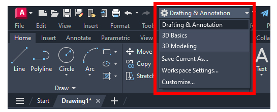
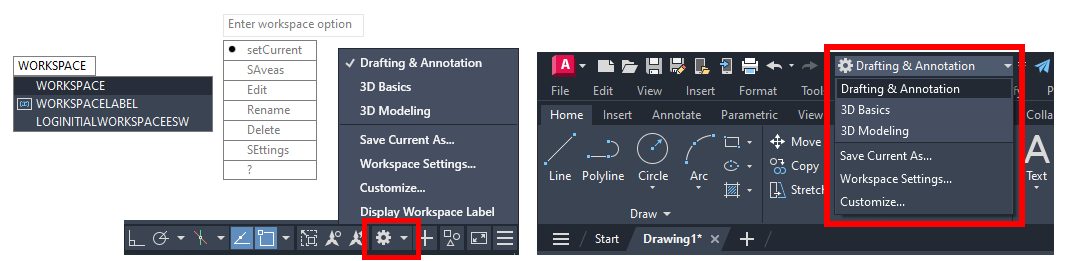
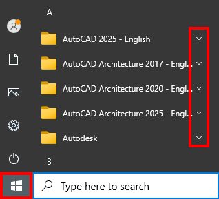
Today, our adventures again take us outside of the interface and into the Windows® Start Menu. The menu can be accessed by clicking on the icon below, just to the side of the search box, or by simply clicking the Windows button on your keyboard. Since you have your scorecards out, the Tuesday Tip about startup switches (hilariously entitled “Start Me Up” and referencing the addition of the Start Menu back in Windows 95, and the Rolling Stones for good measure) also didn’t involve the interface.

The menu contains program groups sorted alphabetically. The Autodesk groups are shown below. Your list may differ from mine depending on what you have installed. Notice they all use a folder as an icon. As such, they each have an expandable menu that can be accessed with the down arrow.

Screenshot of Autodesk menu

Autodesk Folder Group

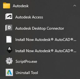
We’ll focus on two of the groups in my list. First up is the Autodesk group. Here, you’ll find a link to the Autodesk Access program – which can come in handy if you find it difficult to tell one tiny icon from another from the taskbar’s hidden icons menu.

Again, depending on what you have installed, you’ll find things like you see in the image below. There are a couple of old installation shortcuts, the ScriptPro executable that I used in the aforementioned Start Me Up blog post, and the old Uninstall Tool that came with the 2017 ACA I have installed.

Screenshot of Autodesk folder group

Expanding the AutoCAD 2025 folder group will yield several very handy tools, and in general, are the intended subject of this post. Have you ever needed to attach a digital signature to your drawings? Did you even know you could? If you have a digital ID or certificate on your computer, this is where you go to add them.

Next is the AutoCAD program file. Why would you ever need to access it from here? Let’s say you’ve accidentally deleted your desktop icon to AutoCAD, and need to recreate it. Right-click the program icon, expand the More menu, and select Open File Location. An Explorer window will open with the executable highlight. Right-click on that, expand the Send To menu, and select Desktop (create shortcut). Badda bing, your shortcut is back on your desktop.

Screenshot of AutoCAD program folder

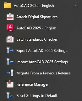
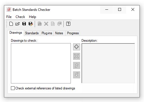
Next up is the Batch Standards Checker. Are you one of those who have tried implementing the standards-checking tools only to have your users revolt because of the constant popups and interruptions? Well, you can still apply your DWS file(s) to your templates and use the batch checker here to run a report without alienating your users.

Screenshot of Batch Standards Checker

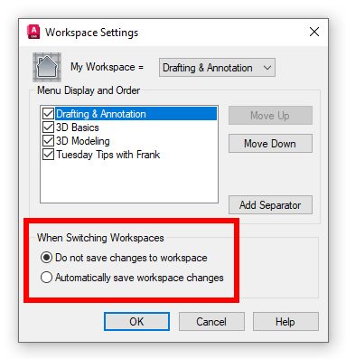
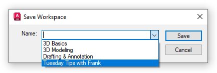
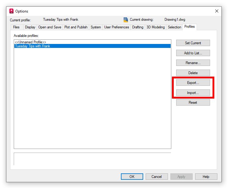
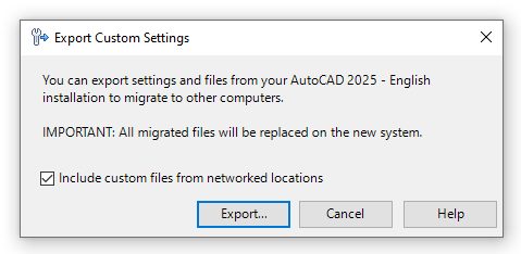
The next two icons allow you to export and import settings and files from the version’s group you’re in (in this case, 2025). You can use the generated zip file to migrate to another computer’s installation as long as they’re the same version. Before you rely on these tools, I suggest you click on the Help button and make a note of what files are included and what files aren’t. You may thank me someday for that hint.

Screenshot of import and export settings

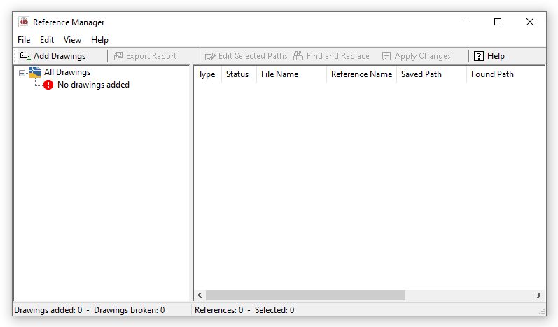
Next is one of my favorites, the Reference Manager. AutoCAD’s pathing management for reference files has improved dramatically in the last few releases. But, as with most things relating to CAD management, the solution usually has to be applied to multiple files at the same time. Enter the Reference Manager. If you’ve ever had to do this, you’re probably already familiar with this powerful tool.

If you decide to try this tool, let me first offer you this caveat: Make a copy of a smaller portion of your project to tinker with. It is extremely powerful, and you can do more harm than good if you don’t know what you’re doing. Again, future-you may thank me someday.

Screenshot of Reference Manager

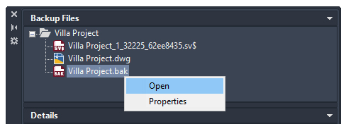
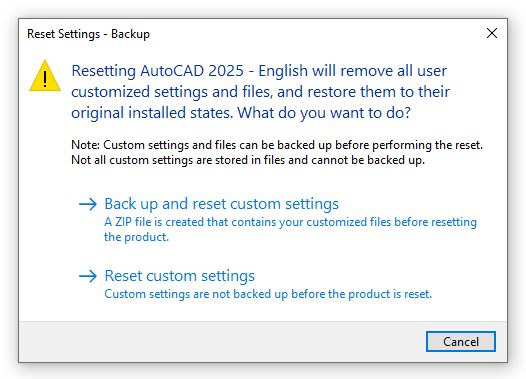
The final tool in this program group can also be quite useful. And guess what? It, too, is very powerful and potentially dangerous. As such, I’d suggest choosing the backup and reset option. It will restore your AutoCAD back to its original, out-of-the-box configuration, so beware.

Screenshot of reset settings

Wrapping Up

How’s that for a lot of tools that you may not have even known about? Yes, some are dangerously powerful, but as long as you’re careful and you know what you’re doing, that power can help you tremendously.

And now that we’re done, you can change that scorecard to three tips that don’t involve AutoCAD itself.

More Tuesday Tips

Check out our whole Tuesday Tips series for ideas on how to make AutoCAD work for you.

AutoCAD 3D Navigation and Visualization: Tuesday Tips With Frank | AutoCAD Blog


AutoCAD is often considered a 2D CAD software product, but it also has an extremely robust 3D environment. Accessing it is as easy as switching to one of the two 3D workspaces included by default. But, like moving into a new neighborhood or going to a new school, one of the first things you need to do is learn how to get around, and the 3D world of AutoCAD is no different.

You’ll be glad to know that zooming and panning in 3D work the same way as they do in 2D, so you’ve got a bit of a head start. You’ve probably already noticed some of the 3D viewing and navigation interface elements that bleed into the 2D world. They can be used there, but they’re really not very useful, so chances are you’ve ignored them. But, in 3D, they are useful, and they’re the subject of today’s post.

Please refer to the image below. The widgets in the upper left labeled as #1 are technically called Viewport Controls. The #2 item is the View Cube, and #3 is the Navigation Bar (or NavBar for short). There are some other places to find these and other tools, but today, we’re paring it down to these three, along with some keyboard and mouse methods.

Screenshot of AutoCAD Viewport Controls

Viewport Controls

Let’s start with the Viewport Control tools. There are three parts to it, and it’s an extremely efficient way to interact with your 3D model. The left widget brings up your Viewport Controls, the center one contains your View Controls, and the one on the right lets you quickly specify your Visual Style.

Screenshot of AutoCAD Viewport Controls

The following image shows the popup menu for each of the three widgets. As a 2D user, you probably equate viewport configuration to layouts. However, in the world of 3D modeling, setting up different views in Model Space can be pretty helpful. I wrote about it here on our blog as part of my Tuesday Tips series. In fact, I’m using the same model for this post as I did then (sometimes, the fine line between efficiency and laziness is a bit blurry with me.)

The View Controls (middle) is an extremely efficient way to quickly switch to a preset view of your model. Setting one takes just two mouse clicks. You can choose between all orthographic projections or from four isometric views.

The same can be said for setting a visual style. Depending on your model and workflow, you may want to change how it appears. Most of us modeling in 3D AutoCAD will have a favorite and just leave it that way. Experiment with each, and no doubt you’ll find a favorite also.

Screenshot of AutoCAD Viewports Popup Menu

Let’s set the top view of our model to be shown in the SW Isometric view and its visual style to be Shaded with Edges. When you set the view, some of the interface elements will change. I’ve either enlarged them or pointed to them in the image below. The Viewport Controls widgets will change to reflect the current setting, the View Cube will rotate to show the current view, the cursor will change into its 3D style, and the UCS icon will change.

Screenshot of 3D part with AutoCAD Viewport Controls

View Cube

Let’s now consider the View Cube. It is yet another very efficient way to change your view to a preset. Without delving too deeply into how it works (that might be a future Tuesday Tip), let’s just say that it’s a more visual, interactive way to change your viewing angle. The cube itself is made up of tiles on the faces, edges, and corners that you pick with your cursor to set that view.

You can also select one of the cardinal directions (N, S, E, W) or pick and drag your mouse along the circular compass below the cube. A home icon and a menu dropdown will also appear when you first hover over the View Cube. To change your “home view,” just right-click anywhere on the View Cube, and click “Set Current View as Home.”

AutoCAD view cube

Navigation Bar

Finally, there’s the NavBar, which shows up on the right side of the drawing editor and below the View Cube. I’m only going to talk about one of the tools within it. But it consists of – from top to bottom – the steering wheel tools (yet another full blog post of its own), pan and zoom, the Orbit tools, and, at the bottom, the Show Motion tool. Let’s focus on Orbit.

Notice there’s a little drop-down arrow just below the icon. Clicking it will allow you to set your Orbiting to a constrained orbit, a free orbit, or a continuous orbit.

Screenshot of navigation bar in AutoCAD

Again, you’re invited to try all three, and no doubt one style will become your favorite. To read about the differences between these, go to the help page on the subject.

Keyboard/Mouse Combos

With all that having been said about the interface tools, in reality, you’ll be like most users, and you’ll do all of your navigating with either just your mouse or with mouse/keyboard combos. You already probably pan and zoom with your mouse (and if you don’t… why not?).

When you’re in a 3D view, your depressed scroll wheel becomes the 3DORBIT command when used in conjunction with your Shift key. So, there’s no slowing yourself down by taking your eyes off your work to hunt down an icon. Your hands are already in place, so use them! Do you like to use Free Orbit? No problem, just add the Ctrl key, making it a Shift/Ctrl combo with the mouse wheel.

Rotating part in AutoCAD

Get Going With 3D

Hey, it’s a 3D world out there, and if you’re still using AutoCAD as just a 2D tool, there’s probably a good chance you’ll be using a 3D workspace sometime soon. Now’s a good time to get familiar with your new neighborhood and to learn how to get around efficiently.

All the methods I’ve discussed today are great to know. Try them all out and find your favorite methods. When you do get the call to work in 3D, you’ll be ahead of the game from the beginning.

More Tuesday Tips

Check out our whole Tuesday Tips series for ideas on how to make AutoCAD work for you.

Top 10 Tips to Become an AutoCAD Power User: Tuesday Tips With Frank | AutoCAD Blog


We’ve done a lot of AutoCAD tips over the years. In fact, we’re approaching a milestone later this year (stay tuned). We thought it would be worthwhile to pick out some that can help you become a power user more quickly. You’ll even get links to blog posts that go into more depth on the topic.

So, if you’re interested in upping your game, here are some tips to help you become an AutoCAD power user.

Some commands in AutoCAD may not be used as often, so AutoCAD provides a quick refresher on how they work.

If you hover over a command in the Ribbon, the short ToolTip will appear. If you keep hovering over the command icon, the extended ToolTip will appear.

An explanation of the command is given, and an illustration of how to use the correct input sequence is provided. Occasionally, the image is even animated for 3D commands. And you have a lot of flexibility on how they’re displayed.

Screenshot of circle and AutoCAD tooltips

Bonus Tips:

Tiptoe Through the ToolTips: Tuesday Tips With Frank

Rollover ToolTips: Tuesday Tips With Frank

A Grip is often faster than a command to edit an object. Depending on the object, the default action is usually either Move or Stretch.

Hovering over the Grip displays other editing options, depending on the object. To launch an edit command, simply select one from the pop-up list or click on the Grip for the default action. Hold Shift while selecting multiple grips.

When a grip is active (a “hot” grip), you can select it and right-click on it to access additional options like Rotate, Scale, and Mirror. In addition, you can specify a basepoint or reference distance, as well as copy the object as you edit it. All of this can be done directly from the selected object.

Bonus Tip:

Have You Tried: AutoCAD Grips – Just Grip It!

3. Take advantage of AutoCAD keyboard shortcuts that can improve your productivity

  • Bypass the Enhanced Attribute Editor to quickly edit an Attribute. Hold down the Control key when selecting the Attribute, and it will highlight similar to Single Line Text for editing.
  • Clean up corners quickly using Fillet or Chamfer by holding down the Shift key when selecting the second object.
  • Hold down the Control key when selecting an object to override any active Lock UI settings and move or close palettes or toolbars.

Bonus Tip:

Learn about all the AutoCAD keyboard shortcuts.

Contextual popup menus are a productivity enhancement favorite. The commands in the menu will be specific to your selection since they’re contextual.

With this method, a single, quick right-click will still function as ENTER, but if you hold down the mouse button longer—a quarter of a second by default—you’ll get the contextual popup menu instead.

Right click menus in AutoCAD

Bonus Tip:

With the time-sensitive, right-click feature, you can have the best of both worlds if you use a mouse to right-click as ENTER. Simply call up the Options dialog box, select the User Preferences tab, and then select the Right-Click Customization button. The control for time-sensitive right clicks will appear in another dialog box.

5. Avoid endless project folder navigation by setting Places in the Open dialog

Whenever you have multiple icons with the same name – like “CAD” – you can right-click the icon, select Properties, and change the name to something more meaningful.

AutoCAD Places

Bonus Tip:

Favorite AutoCAD Places: Tuesday Tips With Frank

6. Identify the differences between drawings and Xrefs with DWG Compare

DWG Compare allows you to quickly view the differences between drawings. All objects in both drawings will be shown as gray, those not in the current drawing will be red, and those only in the current drawing will be green.

The comparison feature has also been incorporated into Xrefs. Don’t waste time with endless email or DM threads trying to figure out what was updated. When you get the notification that something has changed, let Xref Compare show you what is different.

DWG Compare can also insert Revision Clouds, which may speed up your change process by pre-defining color, style, and size preferences.

Bonus Tips:

DWG Compare – Dare to Compare: Tuesday Tips With Frank

Xref Compare: Tuesday Tips With Frank

7. Use Quick Select to easily select multiple objects based on their properties

The Quick Select dialog allows you to build powerful queries to quickly select only the objects you want. You can access the QSELECT command at any time from the right-click pop-up menu.

Do you need to find every Circle with a diameter of 4.25? Every Polyline that is not closed? Every Block instance whose Z scale is higher than 1? All this and more are easy to achieve by using Quick Select.

Selecting all matching entities with QSELECT allows you to perform edit commands or modify common properties across the set.

QuickSelect in AutoCAD

Bonus Tip:

AutoCAD Quick Select: Tuesday Tips With Frank

8. Speed up your workflow by copying objects from your external references with the Copy Nested Objects command

Copy objects from an Xref into your drawing without opening the Xref, copying to the clipboard, closing the Xref, and pasting it back in.

You can reach directly into the Xref to select the objects you want to copy with the Copy Nested Objects command. It’s found in the Additional Tools pulldown of the Modify panel of the Ribbon.

Bonus Tip:

You also won’t need to open the Block Editor, as Copy Nested Objects works on Blocks, too.

NCOPY – Swipe Text and Objects From External References: Tuesday Tips With Brandon

9. Customize command aliases to better suit you with the Alias Editor

You can change the default command aliases in AutoCAD to match your preferred one. We’re all different, so if your mind says “C” means Copy instead of Circle, go ahead and change it.

In the Tools panel of the Express Tools, select Aliases Editor to add, remove, or edit command aliases. Click Edit and remap either “C” or Circle to match your preference.

In a similar fashion, you can add aliases to your favorites. For example, you might often use PDF Import. Just click the Add button, choose an alias, and map it to the PDFIMPORT command.

Bonus Tip:

Be the Office Rock Star With the AutoCAD Command Alias Editor: Tuesday Tips With Frank

The Insert View tool is located in the Layout tab of the Ribbon. You can select the View you want and then drag it onto your layout using the Insert View tool.

When you drop the View into your Layout, it will automatically scale itself based on the Annotation Scale. You can also set the scale before dropping the View into your Layout or use the triangular scale grip when it is placed.

This method saves you the important step of locking the Viewport, as it does it automatically for you!

Named Views in AutoCAD

Bonus Tip:

Named Views – An Old Dog With New Tricks: Tuesday Tips With Frank

More Tuesday Tips

Check out our whole Tuesday Tips series for ideas on how to make AutoCAD work for you. Do you have any favorite AutoCAD tips? Tell us in the comments!

Save Your Settings With Layer States: Tuesday Tips With Frank | AutoCAD Blog


In my last blog, I showed you how to use the various filtering mechanisms to better manage your layer list in AutoCAD. I wrote a lot about “how” to do it. But other than better managing a large layer list, I wrote little about “why” you would do it. Of course, the answer is probably because you need to either change the visibility of a group of layers or alter their properties.

I’ll use the furnished AutoCAD Floor Plan Sample drawing for today’s example. Naturally, everyone’s scenario will be different, but imagine you’re an HVAC designer in an AEC studio. You use the architect’s floor plan as your base file for your HVAC plan. (Granted, you would probably have the structural and reflected ceiling plan, too, but we’re just imagining, remember?)

You don’t want all their furniture, cubicles, etc. and your standards say that the HVAC plans should have the walls to be AutoCAD color 8 – or grayed out.

AutoCAD floor plan screenshot in color

Using various tools, and hopefully, the filter tools we learned about last time, you go about turning things off and changing the necessary layer colors to 8. Now, you have the architectural base layers set for you to start your design. Since you just spent your time performing this task, chances are you don’t want to do it again. That’s where Layer States comes in handy. You can save the current layer settings to a named list within the drawing so that it’s quickly restored if some well-meaning co-worker changes them for you.

OK, since we’re imagining things, what if this was just the first floor of a multi-story building? You can even import these settings into any subsequent floor to design around. Not only will that remove repetition and potential human error, but it will also increase efficiency. More on that in a minute.

Layer States Manager

You’ll launch the Layer States Manager dialog from the Layer Properties Manager palette. It’s the third icon in the upper left corner of the palette.

Screenshot of Layer States Manager icon in AutoCAD

Clicking it will display the Layer States Manager dialog, which is probably empty to begin with. The first thing is to create a new state and give it a name. These steps are probably self-explanatory.

Screenshot of Layer States Manager dialog

Once you dismiss the New State save box, your state will be listed in the States panel. Think of what you’ve just done as taking a snapshot of your layers’ display and property settings.

You’ll have a lot of control over what layer settings are restored, but you’ll have to expand the dialog. Click on the chevron in a circle next to the Help button. The dialog will expand, and you’ll be able to set up a custom set of visibility or properties to restore. You can leave the side panel expanded or contracted as you wish.

Once you save your drawing file, the layer state will still be there, waiting for you or someone else to restore its settings.

Screenshot of chevron to expand dialog box

Importing and Exporting Layer States

Remember the multiple-floor scenario we made up? You can easily export a Layer State to an external file for use elsewhere. Just select the desired state from the Layer States list and click on Export. You’ll get a File Explorer window where you can choose the location for the state. The resultant file will have an LAS extension.

Importing works the same way. You navigate to your file’s location, select it, and click open. However, remember to change your file type pulldown to LAS.

Screenshot of .las file extension

Notice that you have other choices. If you don’t want to go through the overhead of creating an LAS file, you can select a DWG, DWS, or DWT that has at least one state in it. You’ll get a separate dialog allowing you to choose the state you want.

Once the import is successful, you’ll receive a dialog asking if you want to restore the state you just imported. Choose wisely.

Import dialog box

Summary

Personally, I like the idea of writing external LAS files. What a tremendous backup opportunity – but that’s the CAD manager in me. In fact, I used to set up Layer States in my project templates so that my users never had to go through the manual process of setting visibility and properties.

Hey, it takes time to set up your layers correctly for your design tasks. But don’t do it more than once if you don’t have to. Save those settings into a layer state and take a moment to write them out to a LAS file. Because if we know anything in our industry, we know that “things” happen.

More Tuesday Tips

Check out our whole Tuesday Tips series for ideas on how to make AutoCAD work for you. Do you have any favorite AutoCAD tips? Tell us in the comments!

Control Your Large Layer List With Filters: Tuesday Tips With Frank | AutoCAD Blog


Layers. They’re a core feature any AutoCAD user learns about early on. After lines, arcs, and circles, along with how to modify said items, we learn about layers to help us better organize our drawings.

A well-designed layering standard is one of the key components of a design department’s efficiency. But what happens when that layer list becomes so large that it becomes unmanageable?

Imagine bringing a master plan together in an AEC office by bringing in all disciplines as Xrefs. You can suddenly have thousands of layers to manage. That’s where today’s topic comes in—it’s called Layer Filters.

Property Filters

You can create two types of named filters: property filters and group filters. One is more complicated than the other, but both can be very useful. Let’s look at property filters first.

First things first… open the New Property Filter dialog from the icon in the upper left corner of the Layer palette. It’s the one that looks like a folder with a little funnel.

Screenshot of property filter in AutoCAD

Now, it’s time to build your filter. You can use any of a layer’s properties to filter your results. I’ll be building a filter that only gives me layers that have the string “A-Flor” at the beginning and are either red or cyan in color. You first want to give it a name, as you’ll see it listed in the filters panel of the palette when you’re done. I’ll name mine Arch Floor.

Now come the property filters. Since I’m interested in the layer’s name, I’ll click on the Name column in the first row. You’ll see it’s pre-populated with an asterisk. If you’re unfamiliar with wildcards in AutoCAD, you might want to refer to one of my very first Tuesday Tips, where I discuss them more in-depth. I’ll specify the string “A-Flor*.” As I do, you’ll see the layer list begin to change, showing only those layers that match the new criteria. Next, I’ll click in the first-row field of the Color column. A small glyph will display on the right side. Click it to bring up the Select Color dialog. Select the red swatch and click OK. You’ll see your filter preview list now only shows A-Flor layers that are red. Congratulations. You’ve just built a logical AND query. That’s an important thing to know about this dialog. The first row of filters (I could have added any red A-Flor layers that are Thawed) is always a logical AND – in other words, all filters must be true to display a layer name.

Screenshot of layer filter properties in AutoCAD

But we said we wanted all A-Flor names that were either red or cyan. That’s where your subsequent lines come into play. They are logical OR statements. You’ll want to keep the first row’s filters, so let’s duplicate that row. Right-click anywhere on it and select Duplicate Row.

Now, I’ll change the red color to cyan. Just like that, I have what I was after. Click on OK to save your filter. It will immediately show up as the active filter in the layer palette.

Screenshot of active filter in layer palette in AutoCAD

Group Filters

Group filters are much easier to create. The icon is next to the properties filter – without the funnel.

Screenshot of creating new group filter in AutoCAD

This type of filter is just a name, drag, and drop operation. Let’s say we wanted a subset of our property filter containing just red A-Flor layers. Click the icon, and a new filter will appear in the palette, ready to be named. Since it’s now active, the layer panel will show no layers. It’s up to you to find what you want and populate it. I’ll return to my property filter, select only the red A-Flor layers, and drag them into the new group filter.

Yeah. It really is just that easy.

One Last Thing

There’s a very handy checkbox at the bottom of the filters panel in the palette. Check it to invert the results of the filter list. In the image below, instead of getting red A-Flor layers, you’d get those that are not red A-Flor layers.

Screenshot of checkbox at bottom of filter panel in AutoCAD

OK, two last things… remember earlier that I said you could have thousands of layers in our example scenario? If you ever do, you’ll notice that they probably won’t sort alphabetically. That’s controlled by a system variable called MAXSORT. Its default value is 1000. If you have 1001 layers, they won’t automatically sort. Set it higher to make it sort again. But not higher than 32767 – which is, of course, (nerd alert) the maximum value of a 16-bit signed integer.

So, don’t let a massive layer list overwhelm you. Take control of what you see by utilizing property and group filters.

More Tuesday Tips

Check out our whole Tuesday Tips series for ideas on how to make AutoCAD work for you. Do you have any favorite AutoCAD tips? Tell us in the comments!

AutoCAD Workspaces and Profiles: Tuesday Tips With Frank | AutoCAD Blog


Screenshot of AutoCAD

One of the things I liked about AutoCAD when I began using it way back when was that it was designed to be tailored to how you would use it. It wasn’t intended for only drawing floorplans, printed circuit boards, or machined parts, although it could do all those things. The idea was for you to customize it to fit your needs.

Fast forward to its modern incarnation, and that element hasn’t changed. Oh, there are all kinds of specialized offspring, but even the toolsets are meant to be tailored to how you use them. Whether it’s which palettes you have on (and where) or how you view tooltips (or not), these settings all make up your customization of AutoCAD and saved in a couple of places.

Most users are probably aware of these, which we call Workspaces and Profiles. But what are they exactly, and how do they differ? I find that’s often a confusing subject for new users. Today, we’ll look at what each one is, what it contains, and how to use them to your advantage.

AutoCAD Workspaces

Ask most AutoCAD users what customization means to them, and they’ll talk about the user interface. What palettes are displayed? Are they anchored or floating? Auto-hidden or not? Maybe it’s the display state of the Ribbon, or perhaps you like using the old menubar in conjunction with toolbars. All these UI elements can be saved in a workspace, and a workspace is saved within a CUIx file.

Notice I said, “can be.” It doesn’t happen on its own; it requires you to set it up. Let’s look at what that means. First, you can access the commands you need to manage your workspaces in three ways.

The most common place to find your tools is via the status bar. Just click on the gear icon. You can also add Workspace to your Quick Action Toolbar (QAT) and access it there. And, as always, you can also type it in.

Screenshot of drafting and annotation workspace in AutoCAD

I want to concentrate on two of the commands in the menus. The first is “Save Current As…” and the other is “Workspace Settings…”.

We’ll start with Save Current As. There are two schools of thought on creating a new workspace. Some people like to create a workspace (which also sets it as current), then set up the UI as they please, or they’re like me and set up the UI first, then save it as a new workspace—both ways work.

The other important tool to know about lies within the Workspace Settings dialog. Yes, you can choose the active one from here, change the display order, or even add a separator, but the radio buttons at the bottom are the key to managing your Workspaces.

You can either have AutoCAD automatically save any changes you make to the current workspace or not. Choose the latter, and it’s on you to save any changes yourself.

Screenshot of how to save changes in AutoCAD

“But Frank,” you’re saying, “there’s no Save in the menu, just Save As.” I get it. But don’t worry. Use the Save Current As, and you’ll find that the Name field also has a pulldown menu. To save any changes, just select your workspace and save it. It’s kind of a two-in-one dialog!

Screenshot of how to select workspace to save in AutoCAD

AutoCAD Profiles

The second part of the customization puzzle is your profile. It contains things like the background color, command line font and color, cursor size, pickbox size. It’s pretty much anything that’s found in the Options dialog, including path information.

Your computer’s registry stores all this information. And, unlike a workspace, you can export all these settings to an external file (extension of ARG) to use as a backup or to import into another AutoCAD installation. In fact, if you were to open an ARG file, you’d see that it is just a lot of registry keys and values.

Unlike workspaces where you decide how changes get saved, a profile saves any changes automatically. But if you want that external file for a backup – you know, just in case – you have to remember to do it yourself. That is, unless you had me as your CAD Manager, as I put in some start-up AutoLISP code to export a new version every two weeks, because again… things happen. I always find it’s better to be the hero in those situations than to be a goat.

Screenshot of export and import buttons in AutoCAD profile options

Summary

So, there you have it. Pretty much every interface element is stored in a workspace or a profile. Now that you know which one contains what and you have a basic understanding of how to manage them, you’re on your way to having better control of your AutoCAD customizations.

More Tuesday Tips

Check out our whole Tuesday Tips series for ideas on how to make AutoCAD work for you. Do you have any favorite AutoCAD tips? Tell us in the comments!

AutoCAD Fields and Dynamic Data: Tuesday Tips With Frank | AutoCAD Blog


In my last post, we used AutoCAD fields and custom sheet set properties to automate title block information. Today, I’m going to demonstrate a way to automate a callout or label by using a little-used but very powerful feature of fields.  

I’ll assume you have at least a working knowledge of using AutoCAD fields, so this won’t be a deep dive into them but instead focus on a particular feature. Let’s set up a simple scenario and let your imagination turn it into something you’re familiar with. You have a closed object of some kind in your drawing. Maybe it’s a pool, a pond, or a parking lot… and you have to label its total area in some way. That may be via a multileader, a label block with attributes, or it may be somewhere in a block of notes. Have I got you thinking yet? 

Now, here’s the kicker. During the design phase, that closed feature will change its shape, thus changing its total area. Or maybe it’s in a prototypical drawing and changes for every project it’s used in.  

If you’re using a static callout of that area, you’ll need to query the feature whenever it changes and subsequently edit the callout to reflect the new area. Trust me when I tell you that it won’t take very many times doing that to make it get old. This is where an AutoCAD field can come to your rescue. 

The Object Is Your Objective

By my count, there are 50 field names available from the Field dialog box, and they fall within seven categories. You can leave the category set to All and choose what you want from the entire list, but most people prefer to find and set their category first, thus paring down the list. Since the enclosed feature in our drawing is an AutoCAD object, choose the Objects category.

Screenshot of objects category for AutoCAD fields

You should now see only the six field names in the category. All are useful in their own way, but we’re after the Object field for this exercise. When selected, the dialog will change to offer other options. Our next step will be to select the closed feature we’re working with, so select the small select icon next to the Object Type box and select the closed feature. The middle property panel will now be populated with all the properties of the polyline available to you.

Screenshot of Object Type Box with AutoCAD Fields

In this example, we’re labeling the total area of the object we’ve selected, and conveniently, Area is at the top of the list. Select it, and make sure the formatting is what you want from the Format box on the right.

Pro Tip: Need some additional text like a prefix or suffix? Click the Additional Format button for these options and more!

Screenshot of Additional Format with AutoCAD field

Now, with the proper field applied to the callout of your closed feature, it will update whenever its shape is edited. (Just remember the rules on updating fields. I suggest a quick regen).

Not only does this method cut out the continual querying and editing steps, but it also removes the possibility of typing in the wrong value. We humans are quite prone to mistakes, you know – at least this one is.

My example used the area property of a polyline. It could have been the length of a path through a park or even the name of an Xref. The point is to keep this nugget in mind should you ever have to call out a property of an object. It might just save you a lot of work and keep those pesky typos out of your valuable drawings.

More Tuesday Tips

Check out our whole Tuesday Tips series for ideas on how to make AutoCAD work for you. Do you have any favorite AutoCAD tips? Tell us in the comments!

Sheet Set Custom Properties in AutoCAD: Tuesday Tips With Frank | AutoCAD Blog


I often start these blogs with an anecdote, and today is no different. I imagine something similar has happened to most of you. Your project’s template file(s) have some pre-set information in the title block. The CAD manager sets the engineer’s initials as TAE, as he’s been there for twenty years and his initials are on every set that goes out. Besides, if left to individual users, you’d sometimes get TE, T.A.E., or Tae. You know it happens.

Midway through the project, old Thomas Alva Edison leaves for a new job. You get tasked with updating hundreds of drawings to reflect the new engineer’s initials. Let’s be honest: at this point, you wish you had scheduled that root canal for the day.

Wouldn’t it be great if this task was reduced to a couple of clicks? That’s where today’s topic comes in. With the proper custom properties created in your Sheet Set, that’s what you get: a fix in a couple of clicks.

Sheet Set Custom Properties

I wrote about the benefits of using the Sheet Set Manager awhile back. But I only touched on custom properties, and in all honesty, that’s one of its most powerful features.

Like many things in AutoCAD, you can access the Sheet Set Properties dialog via the right-click contextual menu.

Right-clicking on anything listed in the Sheets panel will get you a Properties entry, but the only place to define custom properties is via the top-level sheet set node. When the Sheet Set Properties dialog is displayed, you’ll see the first type of property available – the four built-in Project Control properties.

OK, handy information, but somewhat limited. The real power comes from the Edit Custom Properties button at the bottom of the dialog.

Screenshot of Edit Custom Properties button for Sheet Sets in AutoCAD

Click it to display the Custom Properties list dialog. We haven’t created any yet, so at this point, it’s empty. On the right are two buttons: Add and Delete. Choose the one that’s not disabled. You’ll finally get to the Add Custom Property dialog. It’s pretty simple; you’ll give your property a name and a default value.

But this is where you’ll also find the two other kinds of Sheet Set Properties. In the lower-left corner, you have two choices. Will this Custom Property be owned by the Sheet Set itself (a global property), or will individual sheets own it?

Screenshot of Add Custom Property button for Sheet Sets in AutoCAD

For our example, I’ll create a sheet-owned property of “Drawn By” – as that may differ from sheet to sheet. I’ll also make a couple of global sheet properties – the total number of sheets and our engineer, TAE. Since this is a tips blog, I have an insider tip for you. Notice there is no Edit button. If you’ve made a mistake, you must delete and recreate the custom property. When you’re done, keep clicking on OK to dismiss all the dialogs and save your settings.

Screenshot of Custom Property box for Sheet Sets in AutoCAD

The Next Step

OK, now you’ve got three types of properties in your Sheet Set… what’s next? Now, it’s time to map them to your title block. You’ll do this using AutoCAD’s fields. Since this isn’t a blog about fields, I’ll not spend much time deep diving into them, but if you’re curious, there are several past posts about them, including this one.

In the image below, I’ve applied the built-in project property of Project No., along with our normal engineer of TAE. Finally, the Custom Sheet Set property of Total Sheets has also been added. Let’s step through the important steps of applying our custom sheet property of Drawn By.

Screenshot of Enhanced Attribute Editor box for Sheet Sets in AutoCAD

In this case, we’re dealing with block attributes, but fields can also be applied to Mtext. Again, highlight the value and right-click to display the Field dialog. The first thing you’ll want to do is select the correct field category. Expand the pulldown and select SheetSet. The panel on the left will populate with all the fields available to you from within a sheet set.

We want to add the drafter’s initials for this sheet, which we applied to a custom property owned by the sheet. Select CurrentSheetCustom (those owned by the sheet set are in CurrentSheetSetCustom); since there are possibly multiple properties, a custom name dropdown menu will appear beneath the Format panel. Choose wisely if you have more than one, note the value that appears in the upper right box, click OK, and you’re good to go.

Screenshot of choosing Custom Property in AutoCAD

Summary

Back to our engineer leaving the company scenario… by using Sheet Sets and custom properties, all you have to do is replace the old engineer initials with the new ones. How’s that for saving hours of work? Trust me, it beats the alternative.

Sheet Sets, their custom properties, and Fields are all underutilized, in my opinion. They offer so much functionality, and you don’t even need to use everything they offer to gain a lot of productivity. In fact, while writing this, I’ve decided to make an aspect of fields the topic of my next Tuesday Tip. So, until then, stay tuned!

More Tuesday Tips

Check out our whole Tuesday Tips series for ideas on how to make AutoCAD work for you. Do you have any favorite AutoCAD tips? Tell us in the comments!

AutoCAD File Types: Tuesday Tips With Frank | AutoCAD Blog


This week’s Tuesday Tips installment is an important topic involving various files. During an editing session, AutoCAD creates several files along with your DWG (or DWT or DWS – they’re all the same thing with a different extension). Some are temporary and go away when you exit the file; others do not. Here we’ll explore these different AutoCAD file types.

Easy Ones to Find

By default, this first group of files is saved in the same folder as your DWG file. When the drawing is open, AutoCAD creates lock files with DWL and DWL2 extensions alongside the DWG. You may not see them, as they are set to be hidden. You can turn on hidden files with the control shown below. They are used in conjunction with the WHOHAS command.

Screenshot of AutoCAD and how to find hidden items and file name extensions

This is also where you’ll find the BAK backup file if enabled. Each time you perform a SAVE, a QSAVE, or quit and save, an exact copy of the drawing file prior to that save is created with a BAK extension. The feature is on by default, and you can find it in the Open and Save tab of the Options dialog (it controls the ISAVEBAK system variable).

Screenshot of where to find BAK file in AutoCAD

Next comes the temporary files that are usually written to your temp file folder. This includes the Automatic Save File Location. Where is that, you ask? There are a couple of ways to find the folder. Again, expand the Automatic Save File Location entry from the Options dialog and Files tab. Highlight and copy the path to your clipboard, then paste it into the address bar of a file explorer window.

Screenshot of Automatic Save File Location in AutoCAD

Or, you can take the easy route and type %TEMP% into the address bar, which will take you right to it. If you don’t keep it cleaned out, you’ll probably see thousands of files there, mostly with all kinds of extensions, many of which are TMPs or some files or folders with no extensions. But somewhere in there, if the autosave feature has been invoked in your drawing session, there will be a file that consists of your drawing’s file name, followed by some seemingly random characters and an extension of SV$. That’s your autosave file.

It’s intended to be temporary, as it will be deleted if you exit your drawing properly. But, if you exit thanks to a crash of some kind, it will remain. Similar to the BAK file, it’s a copy of your file when the autosave was invoked. You could copy it somewhere and rename the extension to DWG, and you’d be good to go. Same with the BAK file. Like the backup creation, autosave is turned on by default and set to 10 minutes (the SAVETIME system variable). That control is in the same place as the BAK file creation control in the Options dialog.

Drawing Recovery Manager

OK, those are the important AutoCAD file types I wanted to cover today. They might just save you a lot of lost work someday, but who wants to remember secret codes, odd locations, name changes, or how to show extensions and hidden files in your file explorer? Back in my early days, when we worked mainly with ones and zeros, we had to know this stuff. But today, there’s an easier way. It’s called the Drawing Recovery Manager.

Screenshot of Drawing Recovery Manager in AutoCAD

If AutoCAD detects that it had previously terminated improperly, you’ll be presented with the Drawing Recovery Manager palette upon restarting it. It will contain an expandable list of all the files that were open when the crash occurred, with each entry containing all the available file types.

You may get the drawing file itself, the BAK, the SV$, or if you got prompted to save before the exit, you’ll get a file with _RECOVER appended. These files will be listed in the order that they were last saved.

Screenshot of Drawing Recovery Manager palette in AutoCAD

The Details panel in the middle of the palette gives you the file’s location and the date and time stamp. Below that, you’ll get a thumbnail preview, if available. It is all handy for you to decide which save file is the one you want to use. And when you decide, now it’s just a matter of right-clicking and selecting Open.

Remember those hidden lock files? If you use the Drawing Recovery Manager, it will handle those for you, as they’ll be left over in case of a crash. If you decide to recover the files manually, you’ll have to delete those, or your file will want to open as read-only—another good reason to do things the modern way.

Summary

Yes, the modern way is preferred. But what if the crash left your system unable to access AutoCAD? These things always happen at the worst time, and if you could only recover your work, a co-worker could take over. What a great time to know how to do it manually. Knowing about these important AutoCAD file types and how to use them just might save the day for you sometime. Let’s hope that’s never the case, however.

More Tuesday Tips

Check out our whole Tuesday Tips series for ideas on how to make AutoCAD work for you. Do you have any favorite AutoCAD tips? Tell us in the comments!