How to Detail Sheet Metal Shop Drawings for Increased Fabrication Accuracy for Companies


A sheet metal shop drawing is technical documentation, an instruction manual, or perhaps a blueprint specifically created for the fabrication of sheet metal parts to be used in an architectural or construction project. The drawing must therefore be comprehensive enough to contain details such as material specifications, welding area, bends, hole positions, space dimensions, and so forth. For structural components that are prefabricated off-site, like sheet metal, just about everything needs to be precise to make sure that the on-site construction process runs without hiccups. Prefabricated components have to fit perfectly in the designated place and for the intended purpose to avoid potentially expensive rework.

In a typical construction project, the metal fabricators are not usually integral members of the engineering or design team. They’re subcontractors hired by the general contractor to handle the sheet metal fabrication task. Fabricators rely on metal shop drawings, which are also often created by an external drafter based on the engineer’s design drawing, to produce the parts as specified.

Even the slightest mistake in the drawing can lead to inaccurate fabrication, compromising the quality of the finished product and putting the structural integrity of the building at risk of premature failure. One of the most effective measures to bring about accuracy in a metal sheet drawing is to simply hire the right professionals to do the job. Cad Crowd is populated by thousands of talented CAD drafters who specialize in the AEC industry and are experienced in metal sheet drawings for big and small projects alike.


🚀 Table of contents


Sheet metal drawing best practices

Whether you’re a CAD drafter or metal fabricator, there are many things you can do to make certain that all the details are correct and clearly illustrated.

Stick to DFM Guidelines

When applied to the sheet metal fabrication process, design for manufacturing services, or DFM, mainly focuses on a number of established rules of thumb as well as exceptions for typical fabrication techniques, including welding, cutting, bending, drilling, punching, and so forth. So long as the drawings are developed in conformity with DFM guidelines, you gain a lower chance of error and a higher level of accuracy.

The main point of DFM is to force engineers (and, by extension, the CAD drafter who produces the shop drawings) to consider fabrication-related matters when designing and illustrating sheet metal, so they can guide the fabricators accordingly. For example, a metal sheet shop drawing should specify the direction of the welding and when or where to use filler electrodes. If the metal part needs staggered welds, the drawing should also mention the length of every pitch, enabling the welder to avoid material warping. Specific tolerances for bending or notches must be clearly mentioned as well.

Given properly identified methods, tolerances, and limits, the metal fabricator can make an informed decision in every phase of the task. Remember that just like the product manufacturing process, metal fabrication also aims for a good balance between quality and cost. Accurate and clear shop drawings contribute to cost-efficiency a great deal. Armed with a professionally-made shop drawing, it’s possible to reduce overheads (by not using a greater amount of raw material than what’s needed), eliminate reworks (which also means no additional labor), and streamline the fabrication job of multiple parts. And at the end of the day, it improves the chances of the fabrication getting completed on time. More details about these technique-related matters are discussed below.

RELATED: Top 30 steel detailing companies for CAD drafting and engineering design services in the US
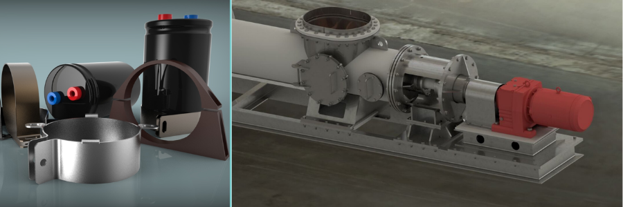
sheet metal design renderings by Cad Crowd shop drawing experts

Material specifications

An engineering design expert’s plan may contain material specifications for the sheet metal parts, and it’s the drafter’s responsibility to translate and interpret the information for the technical shop drawing. There are numerous types of metal materials, from stainless steel and aluminum to tungsten and all sorts of alloys. In fact, each metal has a number of specific grades based on its characteristics, like tensile strength, corrosion resistance, durability, and more. A professional metal fabrication shop probably has a warehouse filled with tons of different metals, so be very specific about what types and grades to use. Thickness also matters, as it directly affects the materials’ ability to cope with mechanical stresses.

Finishes, such as heat treatments or coatings, may seem like nothing but superficial details, but they do serve functional purposes. For instance, powder coating actually triggers a chemical reaction that melts the powder and forms a protective layer on the metal surface. The aesthetic improvement is in addition to this benefit.

Here are some practical tips to provide proper material specifications when working in a CAD environment:

  • It’s always a good idea to make use of the built-in material libraries. Just about every CAD software has a material library filled with a huge selection of materials. You can take advantage of the options for time efficiency and consistency across the fabrication documents. Don’t forget to include industry specifications or standards (like ISO or ASTM) just to make sure that the fabricator only uses materials that meet the performance requirements.
  • In case you need to run an analysis or simulation, specify the material properties, including thickness, density, elasticity, tensile strength, thermal conductivity, yield strength, etc. Assuming the metal parts have to be made of an alloy not listed in the library, you have to make sure that the custom material is well-documented. Also include its properties and characteristics to inform the fabricators exactly what you need. That said, the use of brand-new custom metal alloys is pretty rare unless you’re making high-performance products like cars, weapons, or industrial equipment for engineering design firms.
  • No matter what materials you choose and the associated properties, always use standardized callouts and label them with common symbols. To make things absolutely clear, include the names and grades of the materials in question. Don’t forget to mark them with any relevant codes, if applicable. If there are variations in specifications and requirements (such as edge treatments, finishing, thickness, etc.), highlight the distinctions. Some CAD applications offer color-coding features, which can help mark the difference between two or more similar things. Color-coding is useful for quick material identification.
  • Whether you’re using library materials or custom materials, always attach a datasheet to inform the fabricator of their properties, manufacturer information, and special handling instructions. You can also make annotations directly on the shop drawing to give additional notes. The datasheet serves as a reference in the CAD file; it may even contain suggestions or guides on the use of possible alternative materials.

Last but not least, maintain version control of the shop drawing to keep track of any changes in material specifications. The fabricator should only receive the already-finalized shop drawing, but version control helps you manage updates during the design process. Keeping track of revision history, such as by using a unique identifier to label each drawing, would also prove to be useful during quality checks and the audit process.

Joining and welding instructions

Depending on the shape and geometry of the metal part, sometimes it’s just more practical to join two or more pieces together than to manipulate a single sheet, by either screwing or welding them together. Welding is a proven, reliable technique, but it does take some specialized equipment and skills to get everything within the tolerance for accuracy. If the shape is relatively intricate, welding can be labor-intensive, too. On the other hand, applying screws or fasteners of any sort is much simpler and even preferable, so long as it doesn’t interfere with the metal part’s geometry.

In case welding is the only feasible solution for effective fabrication, the shop drawing expert must specify in detail the types of welds, such as groove, fillet, spot, seam, slot, or plug welds. The location and size of each weld point should also be clearly defined because they may affect the design and structural integrity of the sheet metal. If necessary, annotate the shop drawing with specific instructions such as post-weld heat treatments, temperature monitoring techniques, and quality control measures. All those factors have a major impact on the overall quality of the welds and the finished part itself.

Holes and Cutouts

A sheet of metal usually serves as a single component of an assembly. It must be secured to other parts using the correct types of fasteners to ensure structural integrity. It’s crucial that the shop drawing includes accurate details pertaining to the location, shape, and size of each hole opening for proper assembly. Furthermore, some holes might need specific considerations such as chamfering and deburring; some designs require those edge treatments, whether for visual purposes or simply to prevent sharp edges.

Cutouts are no different. In addition to marking the direction (or shape) and length of cutouts, the shop drawing must inform the fabricators about the specific treatments (if any) required by the design intent. A sheet of metal typically undergoes shearing and punching treatments before it is ready for laser cutting.

RELATED: The 5 stages of prototyping for any new product idea for product design service companies

Bend specification

The key to providing accurate bending information in a sheet metal shop drawing is, first and foremost, understanding what the bends are for to begin with. Metal will deform when exposed to a strong enough force to bend its shape. In the absence of a working knowledge of how metal materials behave under mechanical stress, it would be very difficult to control the deformation. Bending is neither an additive nor a subtractive method. It’s a manipulation technique to modify the shape of metal without adding or reducing the raw material.

Every good CAD drafter has a good grasp of such concepts as k-factors and bend allowances to account for material compression and stretch during bending. The guide provided by shop drawing services allows the fabricators to make the correct calculations (or deductions) and bend the material to produce the intended shape. This is especially important in critical bends, which must adhere to strict tolerances, as they affect the part’s functionality and structural integrity a great deal. CAD software packages like SolidWorks, AutoCAD, FreeCAD, and Autodesk Inventor come with various tools to adjust (or automate) bend deductions.

Assembly information

A shop drawing must contain a list of all components required for the proper assembly of the sheet metal. This listing includes latches, hinges, fasteners (bolts, nuts, screws, etc.), and every other hardware item that comprises the finished product. The quantity of each item must be identified, too. A proper assembly uses all the listed items and nothing more.

Equally important is the assembly instruction to provide a concise step-by-step guide for the fabricator. An instruction informs the fabricator where and how to use the hardware items, the type of fastener for each hole position, the fastening specification or torque, and the correct tool for every step. The guide must be outlined in chronological order for labor efficiency. A detailed assembly guide enables the fabricator to produce a sheet metal that’s both structurally sound and accurate to the design requirement.

Arrange the view for clear communication

A shop drawing isn’t a site plan that contains an overview of an entire project seen from a bird’s eye perspective. It’s also not a visualization simply to showcase how the final metal parts should look when completed. When a CAD drafting expert develops a shop drawing, the final document should consist of multiple sheets of images; each illustrates the part from a particular viewing angle.

In many cases, a single sheet of metal can look like two completely different objects when observed from a different perspective; for instance, the front appears smooth and polished, whereas the back is full of rivets. A complex sheet metal with several 90-degree bends will also look different when seen from either side. Illustrating a sheet metal part from multiple viewing angles leaves no room for guesswork. Among the most common views are:

  • Sectional (or cross-sectional) views: as the name suggests, the view is presented as if you’re looking at a cross-sectional slice of the assembly. The view depicts the interior detail of an assembly, allowing the fabricator to learn and understand any internal structure or mechanism of a metal part. For example, if the sheet is made of two different metals and secured with a screw from the bottom layer, the fabricator can plan the production process to compensate for the design.
  • Orthographic projections: quite possibly the most intuitive illustration of part design, orthographic projections involve creating a set of three drawings – each represents a geometrical detail for the visible components. The three drawings include a top view, a front view, and a side view (either left or right). Every drawing is annotated with material specifications and dimensions to ensure accuracy during fabrication. All three drawings are usually put on the same page for easy comparison.
  • Axonometric views: Like a simple visualization, an axonometric view is a pictorial drawing of the design without any annotation about dimensions. It’s supposed to be a clean illustration of the sheet metal for the fabricator to understand the orientation of each component used. Axonometric views have simplified design details and must be used in conjunction with isometric drawings for sheet metal fabrication purposes.

There are several other views in shop drawings, but the aforementioned three are by far the most comprehensive and commonly used because they can effectively communicate design intent. Many companies have started adopting 3D modeling design services to supplement the conventional CAD drawing.
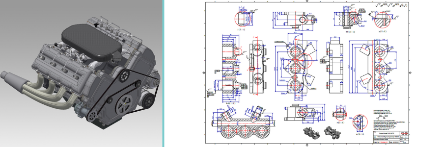
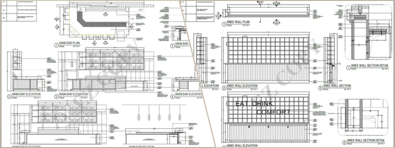
sheet metal design plan and example by Cad Crowd shop drawing freelance experts

RELATED: 15 engineering design constraints that product design companies & engineering firms can’t avoid

Avoid excessive details

Sheet metal shop drawings are essentially instructions for fabricators to produce metal parts. They contain information about material specifications, dimensions, welding techniques, finishes, types of fasteners, and assembly. You can annotate every single component with loads of data in the hope of making things absolutely clear, but sometimes this approach triggers the opposite effect. Instead of being clear, the drawing becomes cluttered and overloaded with details. Missing information is undesirable, but excessive details are no different. Therefore, you should only include details relevant to the fabrication process, nothing less, nothing more.

Takeaway

Engineers and drafters often get carried away to get everything right the first time, when in reality it may take a few rounds of revision until everything is exactly as it should be. Revision isn’t supposed to be a dreadful hurdle; it’s an unavoidable part of a construction project. In fact, you should expect revisions if all the teams and stakeholders involved in a construction project play their roles professionally. Let’s not forget that converting the original design drawings into the more technical sheet metal fabrication plans isn’t as straightforward as it may seem. It’s an iterative process filled with reviews, modifications, refinements, and ultimately approval.

A lot of details must be addressed before the drawing makes its way to the fabrication shop floor. Only when the metal fabricator gets all the required information and is actually capable of translating it into a series of feasible fabrication processes may the actual work begin. But then again, it’s not the fabricator’s job to prepare the details and deliver them in a comprehensive drawing; the responsibility falls on the drafter. Get a free quote today.

author avatar

MacKenzie Brown is the founder and CEO of Cad Crowd. With over 18 years of experience in launching and scaling platforms specializing in CAD services, product design, manufacturing, hardware, and software development, MacKenzie is a recognized authority in the engineering industry. Under his leadership, Cad Crowd serves esteemed clients like NASA, JPL, the U.S. Navy, and Fortune 500 companies, empowering innovators with access to high-quality design and engineering talent.

Connect with me: LinkedInXCad Crowd

HVAC Duct Shop Drawings: The Complete 2025 Guide for Freelancers and Construction Service Firms


Nothing is as important in construction as precision and efficiency. Especially with mechanical settings such as heating, ventilation, and air Conditioning systems, as it really makes all the difference. The presence of small errors in a mechanical system could easily create huge delays or massive inefficiency in completing work for a given client. Cad Crowd has long supported professionals and businesses as the best platform to help bridge such technical gaps through vetted experts in mechanical design services.

Duct shop drawings by HVAC avoid such pitfalls. Special diagrams are called for in the planning, fabrication, and putting up of ductwork systems. Here, we will introduce what HVAC duct shop drawings are, why they are so important in construction projects, and how freelancers and firms can use them to maximize the achievements of the projects in 2025 and many more.


🚀 Table of contents


What are HVAC duct shop drawings?

Detailed technical Heating, Ventilation, and Air-Conditioning Systems (HVAC) duct shop drawings refer to the detailed view of the comprehensive ductwork system of a building. It is more than the ordinary blueprint, as these drawings reveal the exact details related to fabrication and installation needs of ducts, fittings, and components of an HVAC system that are contrary to general construction design drawings. Unlike general construction design drawings, shop drawings give the accurate information required in the manufacturing and installation stages. These are often prepared by specialists in HVAC design services.

Major constituent elements that comprise typical HVAC duct shop drawings:

  • Duct layout: Include the layout and all positions of each duct, together with its overall length.
  • Dimensions and elevations: Measures and heights should be applied to the space correctly.
  • Component information: fittings, dampers, grills, vents, and the rest of the HVAC devices.
  • Material specification: type of material used, such as sheet metal gauge.
  • Coordination: It means that the duct system does not get in the way of another building, such as electrical or plumbing.

Usually done after preliminary design but before construction, these drawings act as a connection between design and execution.

RELATED: Relevance of MEP drafting services for architectural design firms & construction companies

Why are HVAC duct shop drawings important?

HVAC duct shop drawings are not just some sort of requirement; they are part and parcel of any construction that includes an HVAC system. Why is it so?

1. Improves the accuracy and reduces the errors

Shop drawings serve as a guide to the fabricators and installers. There is less chance of error in construction, and teams can clearly view in detail the ductwork layout in order to pick up conflicts ahead of time with other systems, structural beams, or electrical conduits. This will save time and money. For this reason, many teams rely on construction drawing services for accuracy.

2. It ensures code compliance

HVAC systems must follow the codes prescribed by the local building codes and also the guidelines of the specific industries. Shop drawings will ensure that all elements are installed within the law; otherwise, failed inspections would be at a minimum. Services such as code compliance services are critical in reviewing these.

3. Increases efficiency

Shop drawings show the specific details of materials, dimensions, and layouts as they help the contractors to purchase accurate materials, therefore reducing waste and ensuring the HVAC system functions optimally.

4. Facilitates team coordination

Construction of buildings has been a very labor-based and team-based activity, with several trades working side by side on-site. The common reference is the shop drawings; thus, they facilitate high-coordination work for HVAC installers, electricians, plumbers, and general contractors. That’s why many firms turn to MEP drafting services to ensure smooth coordination between trades.

5. Increased client satisfaction

If the installation process goes well and the HVAC system proves efficient, contractors will meet better timelines for the project, even in the clients’ expectations. It can bring about further client satisfaction and recommendations.

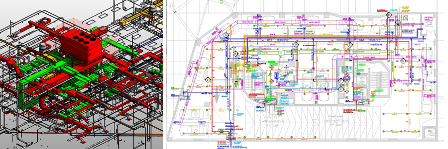
HVAC designs by Cad Crowd architectural design and engineering experts

How to design HVAC duct shop drawings

HVAC duct shop drawings are prepared by a step-by-step procedure that involves designers, engineers, and contractors. Here is how it goes:

1. Preliminary information

Shop drawings will only be prepared after the project design team has passed on the architectural plans, mechanical designs, and specifications for reviewing purposes to ensure that what is being created indeed reflects the proper building layout, height of the ceiling, structural elements, and other mechanical systems.

2. Shop drawings

A draftsman makes use of specialized CADs such as AutoCAD, Revit, or SolidWorks in order to create an outline of the basic layout of the ducting using the design documents. Drafts include dimensions, elevations, and general routing plans. These are typically handled through 2D drafting services for foundational accuracy.

3. Coordination with other trades

This coordinating meeting ensures that no clashing takes place between the ductwork and the other systems. This is considered a clash detection wherein the shop drawings are compared with an electrical, plumbing, or structural layout to avoid clashes.

4. Finalization of drawings and verification

After the coordinated drafts, checking against building codes and all the requirements are provided for fabrication and installation. The drawings are finally finalized.

5. Approval of client and engineer

Final drawings are submitted to the project engineer or architect for approval, such that the stipulated standards of the design project are met at the correct regulatory levels.

RELATED: Ultimate guide in choosing freelance structural engineer for companies and firms

The best freelancing and construction companies practices in 2025

With the approaching year 2025, the requirements for energy efficiency and environmental sustainability related to heating, ventilation, and air-conditioning systems will be more challenging. Freelancers and construction firms offering shop drawings for HVAC ducts should adopt the following best practices in order to stay ahead in the market:

1. Utilization of BIM (Building Information Modeling)

BIM Software like Revit offers quite a lot of facilities for high-end 3D model development in HVAC systems. Visualized clash detection and auto-updation in real-time are done more accurately than in any other common BIM software. With the adoption of BIM, freelancers and firms will be able to offer shop drawings of high quality and thereby get a chance to stand points above their competitors. Teams with experienced 3D HVAC modeling experts are increasingly in demand.

2. Cloud-based collaboration tools

The cloud-based platforms like Autodesk BIM 360 are going to provide an opportunity for team collaboration where all the members can have instant access to drawings and even edit them together. That means coordination may improve, communication delay may be reduced, and thus this would make the efficiency of the project better.

3. Implement sustainable design practices

With ever-stringent energy efficiency mandates, low-energy design of HVAC systems should be developed. Shop drawings should also be provided for energy-efficient features such as VAV systems and DCV. Specialists in energy modeling services are key to integrating these into your plans.

4. Invest in training and certification

Maintain all the industry standards, software tools, and technologies in HVAC. Also, consider certifications through organizations like ASHRAE, the American Society of Heating, Refrigerating, and Air-Conditioning Engineers.

5. Value-added services end

Professionals who go beyond drawings—offering HVAC load calculations, documentation, or commissioning reports—stand out in a crowded market. Many firms work with sheet metal design professionals to extend their capabilities.

HVAC duct shop drawing software 2024

HVAC examples with sectioning and floor plan by Cad Crod freelance experts

RELATED: Overcoming errors in outsourcing with architectural drafting services firms

Quality and efficiency are accomplished in the production of HVAC duct shop drawings with the proper software. Here are the best ones for that in 2024.

  1. AutoCAD – In demand due to its flexibility and feature set, AutoCAD is perhaps a very popular perennial in creating 2D and 3D shop drawings.
  2. Revit – Revit is an example of a BIM software that can create models of 3D HVAC systems, very detailed, coordinated, and precise. Projects with extensive collaboration between several trades are well-suited to be done on Revit.
  3. SolidWorks – Recommended for freelancers who already have an advantage in quality, detailed component design, because advanced 3D modeling capabilities are also supported.
  4. Navisworks – This is the best choice for clash detection and project coordination, as it works best for large-scale projects.
  5. Trimble SysQue – SysQue is an MEP systems solution that integrates with Revit to auto-generate detailed, code-compliant duct shop drawings. Professionals in sheet metal design services often rely on this software to deliver shop-ready drawings.

How to market HVAC duct shop drawing services as a freelancer

If you are one of the freelance shop drawing specialists in HVAC ductwork, it is then easier to market your services amidst a competitive market. There are five things you can do. 

1. Optimize Your Online Presence

Create a professional website that displays your portfolio of shop drawings. Then, you should apply your SEO technique in targeting specific keywords like “HVAC shop drawing freelancer” or “ductwork CAD services” to attract the desired clients.

2. Use LinkedIn

LinkedIn could also be an option for networking connections for construction companies, project managers, and architects. Post case studies, client testimonials, and project updates often to gain credibility and for your profile. Be sure to highlight your freelance CAD services in your profile description.

3. Free Consultations

Offering free consultation initially and a reduced fee for your initial projects attracts new clients. The amount of trust gained through a free consultation drives those clients eventually towards long-term contracts.

4. Industry Forums and Networks

Networking and exposure occur here through forums like ASHRAE, HVAC-Talk, or Construction Specifier. Word-of-mouth referrals become an offshoot from here.

5. Build Strong Customer Relationships

Quality and accurate shop drawings, along with excellent customer service, are the key to customer satisfaction. Their satisfaction will prove to be your best source of referral and repeat business.

RELATED: 10 tips to improve photorealistic 3D renderings for design companies & freelance 3D artists

Wrapping it up

Shop drawings of HVAC ducts will never not be trendy as these drawings provide accuracy, efficiency, and compliance. Together with freelancers aiming to expand their HVAC drafting services and construction firms wanting to streamline their processes, investing hard-earned money in the right tools, training, and marketing strategy sets you up for success in this growing market. Familiarizing oneself with the specifications of code-compliant HVAC duct shop drawings assures interference-free project execution through optimal resource utilization and client satisfaction. This business is built on the latest technologies and developments related to sustainable practices.

How Cad Crowd Can Help

At Cad Crowd, we make it easy for companies to connect with top-tier CAD professionals who specialize in HVAC duct shop drawings and mechanical design. Whether you need 2D drafting, clash detection, BIM coordination, or support for an energy-efficient HVAC system, our network of vetted freelancers is ready to deliver. Cad Crowd leads as the top marketplace to find the best freelance talent. We take the guesswork out of hiring by matching you with qualified experts based on your specific project requirements. Our flexible, project-based approach helps businesses save time, reduce overhead, and get results faster. Ready to streamline your HVAC documentation? Get a free quote from Cad Crowd today and hire with confidence.

author avatar

MacKenzie Brown is the founder and CEO of Cad Crowd. With over 18 years of experience in launching and scaling platforms specializing in CAD services, product design, manufacturing, hardware, and software development, MacKenzie is a recognized authority in the engineering industry. Under his leadership, Cad Crowd serves esteemed clients like NASA, JPL, the U.S. Navy, and Fortune 500 companies, empowering innovators with access to high-quality design and engineering talent.

Connect with me: LinkedInXCad Crowd

Fabrication shop drawing services: all you need to know


What type of services do companies rely on when picking fabrication shop drawing services?

Before any construction begins, numerous drawing sets (each bringing their significance to the project) are prepared. These drawings are then used from preconstruction to post-construction to inform the construction process and ensure accuracy. To this end, architects prepare many different types of construction drawings to represent the overall intent and function of the design.

At the same time, contractors prepare shop drawings to show actual field executables.

These 2D documents are the main deliverables in building large-scale and complex structures and are critical to executing any construction project.

What are fabrication shop drawings anyway?

You would want to use fabrication shop drawings services for technical drawings that detail comprehensive information on a structure or product’s construction, assembly, and manufacturing. If you’re still in doubt, it would be best to expel those right now: these drawing services are essential to the engineering and design processes – they serve as valuable communication tools among fabricators, designers, and engineers.

Fabrication drawings are pivotal, indispensable guides that visually articulate the components and structures slated for fabrication. These drawings serve as navigational tools for fabricators, welders, and technicians to ensure the precise execution of fabrication processes by documenting every piece of functional information. It minimizes the risks of delays or damages and guarantees a seamless construction process.

RELATED: What casework shop drawings are and why architectural design services use them

Fabrication shop drawings should comprise every detail about the materials, tolerances, dimensions, and any other specifications necessary for the fabrication or construction of a product; they’re made to make your life easier as you go through construction.

These drawings from architectural drawing professionals are instrumental in translating design concepts into tangible reality. They offer detailed visual representations encompassing components, dimensions, and specifications essential for constructing diverse structures, machinery, and products. The devil is in the details, and fabrication shop drawings act as a bridge that connects design intent with the practicalities of production, maintaining accuracy throughout the fabrication processes.

Typically, fabrication drawings are the handiwork of skilled draftsmen or CAD designers.

These 3D modeling professionals infuse the drawings with intricate information, including material specifications, welding symbols, and assembly instructions. Acting as a vital means of communication between CAD designers and fabricators, these drawings foster collaboration and streamline the manufacturing workflow. Regardless of the industry – be it construction, aerospace, or manufacturing plants – fabrication drawings are THE guardians of precision, consistency, and standards compliance throughout the entire production lifecycle.

Typically, fabrication drawings are the handiwork of skilled draftsmen or CAD designers.

These 3D modeling professionals infuse the drawings with intricate details, including material specifications, welding symbols, and assembly instructions. Acting as a vital means of communication between CAD designers and fabricators, these drawings foster collaboration and streamline the manufacturing workflow. Regardless of the industry – be it construction, aerospace, or manufacturing plants – fabrication drawings stand as guardians of precision, consistency, and standards compliance throughout the entire production lifecycle.

RELATED: What are Redline drawing costs & CAD drafting rates for construction companies?

They are the linchpin in the effective and efficient translation of innovative ideas into tangible, high-quality products. At their core, fabrication drawings are elaborate illustrations that furnish the essential information required for the manufacturing and assembly of a product. The specific type of fabrication drawing necessary is contingent upon the project’s nature and the unique demands of the manufacturer. This article will explore the primary fabrication shop drawing services used by firms and companies and their purposes and essential characteristics.

shop-drawing-firms

Assembly drawings

Assembly drawings offer a comprehensive overview of a fabricated structure or complex assembly, illustrating the interconnections between various components. These drawings, featuring exploded views and a bill of materials (BOM), guide fabricators in understanding how different parts come together. They play a crucial role in streamlining the fabrication process and ensuring accurate positioning, alignment, and connection of components.

Assembly drawing services provide foundational blueprints that unite diverse components, fostering effective collaboration between design and fabrication teams. They visually represent how individual elements fit together, providing essential information on dimensions, materials, and assembly instructions. Creating precise assembly drawings is imperative for companies providing fabrication drawing services, contributing to the overall quality and functionality of the final product.

RELATED: Hire freelance contractors on demand for affordable shop drawings

Cutting lists

In fabrication drawing services, cutting lists are instrumental in optimizing material usage and outlining dimensions and quantities for efficient fabrication. Particularly in steel fabrication drawings, cutting lists guide fabricators on minimizing waste during raw material cutting, aligning with an increasing emphasis on sustainable manufacturing practices.

Detail drawings

Detail drawings focus on individual components, highlighting dimensions, tolerances, and surface finishes. Essential for fabricators, these drawings provide specific measurements, material specifications, and additional requirements for accurate component production. Detail drawings, especially in steel fabrication, ensure precision and consistency in manufactured parts. Beyond precision, detailed drawings guide the fabrication process, ensuring components align with design specifications. In the realm of fabrication drawing services, attention to detail becomes a necessity rather than a virtue.

Piping and instrumentation diagrams (P&IDs)

P&IDs (piping and instrumentation diagrams), specialized industrial drawings in oil, gas, chemical, and process engineering, depict interconnected piping systems, equipment, and instrumentation. Using symbols and annotations, they represent components, valves, instruments, and control systems, aiding in fabricating, installing, and maintaining complex process systems. P&IDs play a crucial role in guaranteeing the precision and effectiveness of fabricated process systems.

RELATED: How much do CAD drawing services cost for design drafting & architectural blueprints?

Shop drawings

Shop drawings are detailed representations of fabricated components produced in a workshop or fabrication shop. These drawings provide precise information on dimensions, materials, tolerances, and finishes, acting as a vital link between design vision and actual production. In the context of fabrication drawing services, shop drawings from shop drawing experts offer a detailed representation of the product, aiding fabricators and manufacturers in producing accurate and consistent components. This translation of design intent into actionable instructions is vital for structural steel shop drawings, enhancing efficiency and accuracy in the manufacturing process.

Structural drawings

Structural drawings from proficient structural steel detailing professionals are essential for constructing buildings, bridges, and large-scale structures, providing comprehensive overviews of facilities, including dimensions, elevations, sections, and connections. They guide fabricators in accurately placing and aligning structural elements, ensuring stability and safety throughout fabrication and construction.

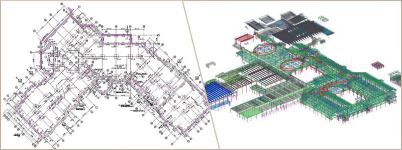
structural-steel-detailing-professionals

Welding and metal fabrication drawings

Specific to welding and metal assembly processes, these drawings offer detailed instructions for welders, showcasing weld types, sizes, positions, and required symbols. They play a crucial role in ensuring the quality and strength of fabricated metal structures, contributing to safety and compliance with industry standards. Welding fabrication drawings guide the welding process, ensuring each weld meets standards for strength and durability, preventing structural failures and accidents.

RELATED: Structural steel detailing services for companies: steel detailer costs and rates

Why work with fabrication shop drawing services?

Fabrication shop drawings play a significant role in the steel manufacturing industry, serving as crucial documents for fabricators, manufacturers, contractors, and suppliers. These drawings, derived from construction papers, are often prepared with the assistance of detailers hired by the owner to provide detailing services.

These drawings from skilled fabrication drawings experts facilitate the fabrication and erection processes for project teams by comprising sections and views with detailed dimensions, welding information, and adherence to fabrication standards. They provide a precise blueprint outlining how the plans should be executed. The accuracy of shop drawings from the fabrication shop drawing service is instrumental in obtaining architectural approvals and ensuring project profitability.

Contractors and fabricators have a vested interest in accurate fabrication shop drawings. The reliance on these drawings enables well-informed decision-making, preventing costly mistakes that could jeopardize the integrity of the building and the safety of workers. Access to high-quality fabrication drawings is invaluable for various reasons.

RELATED: Affordable shop drawings & drafting services by freelancers & contractors on Cad Crowd

1. Accuracy

Shop drawings for steel fabrication drafted by as-built drawings firms meticulously detail the most critical and complex parts of a building. These detailed drawings provide the necessary information for constructing and installing components accurately, ensuring that the buildings adhere to specified criteria.

2. Fabrication standards

Fabrication shop drawing services undergo rigorous standard tests and quality control inspections within the Architecture, Engineering, and Construction (AEC) industry. Skipping quality assurance checks can lead to prolonged construction timelines and increased material usage. Fabrication shop drawings must align with industry standards to guarantee timely delivery to the customer.

3. Foundation

Detailed blueprints in the framing plan provide essential information for determining the beams and columns required to construct the building’s steel frame. This information guides decisions about drilling, cutting angles, and other critical aspects of the construction process.

RELATED: Freelance contractors offer architectural drafting & CAD design services on CAD Crowd

4. Methods for safe drawings and continuous work

Accurate fabrication drawings are essential to avoid delays in construction due to insufficient materials. Timely ordering of supplies relies on precise shop drawings. Ensuring that shop drawings meet industry standards contributes to the safety of workers and enhances the likelihood of a building project’s long-term durability.

5. Splitting into two groups

Two distinct types of detailed drawings aid in construction: shop drawings and erection drawings. While erection drawings illustrate how a building is assembled on-site, shop drawings detail how steel parts are manufactured. In essence, fabrication shop drawings are not just documents but indispensable tools contributing to the success, safety, and longevity of construction projects in the steel manufacturing industry.

How Cad Crowd can help

Fabrication drawing services are indispensable for accuracy, precision, and efficiency in the fabrication and construction industries. Fabrication drawings serve specific purposes, providing essential information for professionals in these fields. By understanding assembly, detail, cutting lists, P&IDs, shop, structural, and welding drawings, industry professionals can enhance communication, collaboration, and overall productivity, ensuring the delivery of high-quality and reliable products and structures.

Cad Crowd can connect you with reliable fabrication shop drawing services that will help your company or firm achieve the desired results for your projects. 

How Do Companies Use Millwork Shop Drawings for 3D Furniture Modeling and Design?


The millwork industry provides clients with quality personalized products, and they must innovate to keep the costs down as much as possible. Companies are now outsourcing millwork shop drawings to cater to this business challenge, which is a consistently winning formula. If you ask any veteran furniture marker, the secret to achieving top-quality millwork is clear communication during the project.

The best way to achieve this is to align millwork drawings with 3D furniture modeling and design using the right combination of technology and freelance millwork drafting and drawing services.

More and more businesses are now realizing that outsourcing millwork shop drawings is a great way to get top-of-the-line millwork drafting at the best costs possible. These service providers are flexible and experienced in handling projects regardless of complexity. It’s easy for them to scale down or scale up resources to make way for the valleys and peaks of a business.

Top millwork challenges in furniture making

Millwork furniture manufacturers often face some significant challenges, which include the following:

  • Compromised expertise and skills

Numerous challenges are associated with bringing on board and training people who can produce the most detailed millwork shop drawings for 3D furniture modeling and design. It leaves most manufacturers with no option but to settle for less. However, manufacturers have realized that if their goal is to continue engaging customers with personalized and brilliant furniture pieces at reasonable costs, they must explore joinery and millwork partnerships with expert firms.

  • Delayed schedules of projects

Acquiring millwork drafting and drawing skills is time-consuming and has a steep learning curve. In-house teams are found to be less flexible when it comes to extended working hours. Without a doubt, this can easily jeopardize a project’s deadlines.

Hiring a team of millwork drafters who are experts in operating numerous CAD platforms can significantly burden manufacturing budgets in terms of exorbitant salaries and training and head-hunting costs. Arranging technological infrastructure regarding software and hardware can further drain finances.

A recurring issue for millwork developers is the constant rework in the joinery drawings throughout the conceptualization and design phases. Flaws identified much later in the production phase can cause a delay in manufacturing deadlines, making project costs shoot to the sky and dragging the projects for weeks or even months.

RELATED: Millwork Drafting and Design Drawings: Rates and Costs for Companies and Firms

How to use millwork shop drawings for 3D furniture modeling and design

furniture1

Millwork shop drawings are not just a critical tool for furniture making but can also be very effective for developing furniture designs. These can help in the recreation of designers’ ideas in 2D graphics and getting the project approved to ensure a seamless and smooth production process.

Millwork shop drawings are not just great for technical manufacturing but can be a great help in communication between contractors and designers. Here are some ways companies can use millwork shop drawings for 3D furniture modeling and design.

Showcase precise dimensions

Millwork shop drawings, more than anything else, are considered the most precise demonstration of dimensions. These include the product’s general size measurements and the dimensions of every part. With the help of millwork shop drawings, designers can ensure that the dimensions meet their requirements and seamlessly fit into their projects.

This type of millwork drawing as a plan section and plan view allows designers to make all the essential home measurements and guarantee that the furniture piece will go well with the room. It is particularly applicable to plan views with furniture layout. 3D furniture modeling services use these drawings to determine the right furniture arrangement and envision how a particular 3D furniture model will look once it becomes part of the interior design.

RELATED: 3D Furniture Modeling Services, Costs, Rates, and Pricing for Companies

Display the functionality of furniture pieces

Millwork shop drawings can also present a clear idea of the functions of the product from the engineering point of view. Thanks to them, millwork experts can prove the durability and usability of their products, which are as essential as the piece’s appearance. Interior designers can then ensure that every project element will function exactly as planned and perfectly suit their brief.

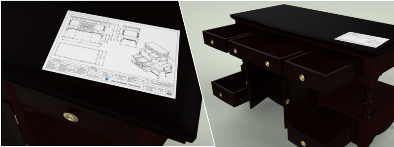
Freelance shop drawing services offer elevation drawings showing every functional possibility of a furniture model. For instance, if it is a locker, the draft will present how drawers come out. On the other hand, if it is a sofa, the client can view the right way of unfolding it. Detailed millwork shop drawings make it easier to examine the mechanisms and fastenings of product models and grasp how things work.

Enumerate the specific materials used

The materials used largely shape how a product looks, so correctly indicating them is vital in the presentation of furniture designs. Millwork shop drawings present all the details regarding the materials used during production. They show complete data for every resource, including the type, name, and the part of the item where it will be used.

These drawings also allow confirmation that every material chosen is in line with the requirements of the designer. They also allow room for making adjustments before the start of the manufacturing process. Once the millwork shop drawings have been approved, the interior designer will know the precise quantity of materials they need to buy to prevent excess or shortage.

furniture2

Present structure quality

Millwork shop drawings are also the most reliable means of presenting the technical elements of furniture design. They help present the structure of the product while establishing its solidity. In particular, these drawings also showcase the overall view of the ordered piece and the quality of its inner parts.

The plan section of millwork shop drawings shows every part of the product’s structure in complete detail and from various views, including top, cut, horizontal, or vertical. The millwork plans also show interior designers how an item is developed and how it functions, allowing the assessment of the construction of the furniture piece in general and the separate parts of the product.

Show the design details

Millwork shop drawings also allow for studying the design details and exploring the furniture fixtures more completely. These drafts highlight not just the engineering specifications but also the design details and the product furnished. This is an effective means to agree on all parts and aspects of the project with the designer and receive their approval.

These detailed drawings are also perfect for the examination of even the tiniest aspects of the furniture. The drafts can show the object’s different parts at a bigger scale from various angles. These also include marks with the materials and dimensions, even for minute details such as nails and bolts that help prevent errors during the manufacturing process.

RELATED: Affordable Shop Drawings & Drafting Services by Freelancers & Contractors on Cad Crowd

Reasons to outsource millwork shop drawings

You can benefit from outsourcing millwork shop drawings for 3D furniture modeling and design. These include the following:

Cost-effective

When you work with a dedicated provider of CAD drafting services, you can have complete assurance that you’re working with someone who invests in employing and training a skilled workforce, infrastructure, and the correct CAD software for millwork drafting and design needs.

It lets you operate lean while enjoying significant savings on operating costs. Several of today’s most prominent manufacturing companies are already enjoying the perks of outsourcing millwork shop drawings in terms of lower project costs.

furniture3

Scalability and flexibility

The initial millwork shop drawings usually change and require several reworks that can lead to additional costs, missed deadlines, and confusion on the shop floor. With its pool of experts, your outsourcing partner can quickly change the drafts within the expected timelines and follow quality benchmarks.

The best CAD partner can also provide resource scalability, which you can quickly ramp up once there is an increase in the workload. You can save costs once the demand returns to normal by dropping off the additional resources. This enables you to choose the projects you wish to take on with no need to worry about the availability of resources.

RELATED: Millwork Drawings Outsourcing by Freelance Contractors on Cad Crowd

How Cad Crowd can help

Millwork manufacturers care about one thing, and that is to offer top-of-the-line products to their customers. It means that they always look to create a hassle-free and effective process. The good news is that you can achieve this through outsourcing. Millwork shop drawings are a great way to present your furniture projects to the designers, gain their design approval, or make the necessary changes before they continue to the manufacturing phase.

Cad Crowd is a great resource where you can find experts in millwork shop drawings perfect for 3D furniture modeling and design.