Share CAD Drawings Securely with View-Only Links


Learn how to share DWG-format CAD drawings easily and efficiently by using view-only links. Avoid the hassles of email attachments, prevent version confusion, and collaborate in real time.

Going into the new year, it’s time to take stock of what’s going well in your CAD workflows — and to discard outdated practices that are bogging you down. Making even a small upgrade in your daily routine can have a big impact.

Your file-sharing practices are a great place to start. Sharing information — both inside and outside your company — is fundamental to collaboration. But when it comes to efficiency and security, sharing methods are not all equal. If you’re still sending DWG files to collaborators via email, you’re wasting time, taking unnecessary security risks, and introducing confusion with multiple file versions. It’s time you learned about a better way to share: A URL that recipients can simply click on to view your file. 

A view-only link is a modern way of sharing CAD content, allowing recipients to always see the latest, live-updated version of the file. While there may be times when you need to convert your DWG drawings to PDF format for sharing, PDFs can only capture a snapshot of the drawing at one particular moment in time; they’re not automatically updated as the drawing evolves. With view-only links, in contrast, any changes made to the file are reflected immediately, making it unnecessary to resend files. 

In addition, with view-only links, you retain full control over the DWG file you’re sharing. You can protect it with a password, set an expiration date, and even revoke access to the file at any time. 

This article explains how CAD drawings can be shared via view-only links. Specifically, we’ll see how view-only links work in ARES, the world’s no. 1 alternative to AutoCAD. You can download a free trial version of the ARES Trinity of CAD software to explore view-only links, and the rich array of other features, for 30 days. 

Click to watch “Free Online DWG Viewing and Commenting with View-Only Links,” and see the process in action.

Sharing information via a link is significantly more convenient than doing so via traditional email attachments. This modern process offers the following advantages:

  • Quick and easy sharing. You can share specific files, or entire folders, just by generating and sending a link. You don’t have to worry about the size or format restrictions of email attachments, even for large files such as drawings. This ease of use also reduces the risk of human errors, such as accidental email transmission of the file.
  • Access to the latest version — always. Once a shared link is issued, the recipient can always access the latest information at the link destination, because any changes made to the file are reflected in real time. This greatly reduces the hassle of exchanging and managing multiple versions of the same file.
  • Real-time collaboration. With link sharing utilizing cloud services, multiple people can view the file simultaneously, even while it is being edited — creating an environment for real-time collaboration and information sharing within a team.
  • Security ensured by access rights. Since access rights can be finely tuned for each file, using settings that restrict who can view or edit it, users can share information while maintaining the desired level of security.
  • A simple way to collect feedback. Even the link users who only have viewing rights can add feedback and validate the file, by using the intuitive commenting and markup tools. Collaborators’ comments and markups display feedback in context, so it’s easier to understand, yet they don’t affect the drawing itself.

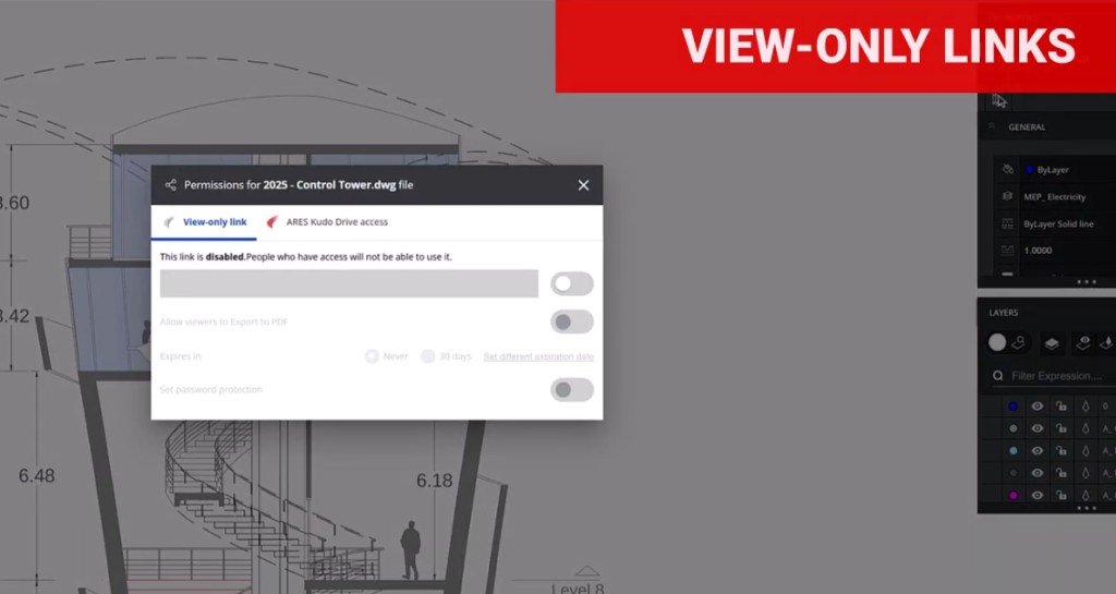
In the ARES Trinity of CAD software — which comprises ARES Commander, ARES Kudo, and ARES Touch — the view-only link feature enables users to safely and efficiently view and provide feedback on shared CAD drawings. By generating a unique link from the sharing options and sending this link to the person you want to share with, you make it possible for that person to view the drawing in a web browser.

View-only links can be created in ARES Commander (the desktop version of ARES), ARES Touch (the mobile version), and ARES Kudo (the cloud version). Drawings can be shared with anyone via the link; the recipient does not need to have an ARES software license.

View-only links have substantial benefits for those sharing and receiving CAD files. Here, we’ll look at just a few of the possible scenarios where this feature can make a big difference.

Use Case #1: Accessing drawings while working from home or on a business trip

The view-only link is convenient when you want to check drawings while away from the office. Since it can be accessed from a browser, the device you’re using is irrelevant — you don’t need the desktop computer or workstation you normally use at work. Also, unlike traditional sharing with file attachments, you can view the drawing with just a click; there’s no need to download any software, or open anything other than a browser.

Notably, you can share a drawing with people who may not be CAD users — such as clients or sales staff — simply and easily. The view-only link allows the link creator to assign viewing permissions only, without editing rights. The link can be configured with an expiration date and/or password, ensuring confidentiality.

Use Case #2: Collaborating in real time with multiple people

ARES is rich in collaboration features for projects. The software prevents conflicting changes by allowing only one person to edit at a time. A mechanism is included where editing rights automatically transfer to the next user if the current editor is inactive for 25 minutes, preventing problems if a user forgets to log out when finished.

In projects where drawings are frequently updated, sharing via file attachments often results in multiple versions and can cause confusion. In contrast, the view-only link always displays the latest version of the drawing, making version management easy.

Furthermore, feedback on drawings can be given through written comments, photos, voice recordings, or stamps, allowing for real-time exchange of opinions.

Use Case #3: Improving sharing security with fine-grained access management

The view-only links feature in ARES allows users to share drawings while maintaining security. Access rights can be flexibly set for each user, giving each individual the ability to edit the drawing or only to view it, for example. Access history is also recorded, so it is clear who accessed the file — and when — at a glance.

ARES can connect to major cloud storage services such as OneDrive, Box, and Google Drive. Saving files to cloud storage provides robust security.

In summary, view-only links are a modern way to share DWG drawings with collaborators, whether they’re CAD users or not. When compared with email attachments, view-only links provide substantial improvements in security and convenience — and they’re very easy to use, for creators and recipients alike. Start your free ARES trial today and discover a secure, modern way to share CAD drawings with view-only links.

Complete Costs of Injection Molding Design, DFM Engineering Rates, & Manufacturing Pricing for CAD Services


Quality injection molding can only happen if you have accurate tooling (mold) to begin with. Although the design – of the mold – essentially follows the geometry of the product or its parts, fabricating the mold presents its own engineering challenges depending on complexity and materials, adding up to the total design cost.

Cad Crowd is one of the leading services in finding the best experts in tooling design, and we’ve collected all we know about its costs (depending on each project) into this one article.

Here’s a simple breakdown of the estimated cost of tooling design services.


🚀 Table of contents


Overview

Task Complexity Estimated price range (USD) Note
Engineering services Feasibility studies and concept development $100 – $250 Hourly rate
Detailed design and structural analysis/optimization $100 – $300
Physical prototyping and testing for manufacturability $500 – $5,000 Per iteration
CAD drawing Straightforward geometry with simple parts $500 – $1,500 Per project
Detailed features and precision components $1,500 – $5,000
Intricate assemblies consisting of multiple parts $5,000 – $15,000
3D modeling Static 3D assets based on well-defined sketches $50 – $150 Hourly rate
Animated models with renderings and animations $100 – $250

To make things much simpler, the following table gives a rough cost estimation based on project size:

Project size Note Estimated cost (USD)
Small Simple products achievable with basic engineering and CAD skills $1,000 – $5,000
Medium Intricate designs requiring advanced 3D modeling and multiple prototypes $5,000 – $20,000
Large Sophisticated or unique products that necessitate comprehensive engineering services $20,000 – $50,000

RELATED: Why prototype DFM services are useful for product design at companies and firms

You should know by now that, like all custom fabrication services, there’s no fixed engineering cost to build injection molds. The exact cost is always affected by a multitude of factors, including but not limited to size, details, complexity, materials, fabrication method, and the company you hire for the job. In general, a small mold for a simple part/design may cost anywhere from hundreds of dollars to a thousand, while an advanced build for intricate objects could cost you tens of thousands.

There are also all sorts of material options, such as stainless steel, aluminum, composites, and even plastic. Steel and aluminum are the most widely used options, as they’re known to have excellent heat distribution and dissipation properties, durability, and suitable hardness for detailed features (the ability to hold shape in high-precision corners). Hard steel is, by far, the most widely used material to build molds thanks to its ability to withstand large-volume production, whereas aluminum is both conductive and cost-effective. It’s worth mentioning that some types of modern hard aluminum (such as 2024 and 7075 alloys) are easily capable of producing 100,000 parts without any major maintenance. Some companies build hybrid molds made primarily of steel and aluminum inserts to get the best of both materials in one package.

A hard aluminum mold costs on average $3,000 for a custom yet basic electronic enclosure design or anything of similar complexity, whereas a machined steel type can go for $20,000 or more. A plastic mold, typically built using 3D-printed polymer, is the cheapest option at around $100 each.

injection moulding plate

RELATED: DFM for new product design excellence: Complete guide for company success

The engineering cost

Injection molding design services are not cheap. Apart from the engineers’ hourly rates, you also have to cover the cost of equipment usage, materials, and labor (fabricators). You don’t have to purchase an entire range of equipment just to build a couple of molds, but the fabricators can’t afford to let you use their machines (whether EDM, CNC machine, or 3D printer) for free. Well, technically, they’re using their own machines, but they do it on your behalf, so you take the bill at the end of the day.

Tooling/mold

Assuming the product parts have already been designed, it’d take around 2 – 4 weeks to build a simple mold and about 6 – 8 weeks to create a complex one. While a custom fabricator can probably take care of the design task for you, there’s nothing wrong with sending them an already-finished mold design, especially if you have the engineering team to do it in the first place. This is to reduce the turnaround time and, ultimately, cost. Furthermore, the engineers know what the final product should look like, so they’re more than qualified to design the mold for it as well. At the very least, send a CAD drawing or STL file to the fabricator to streamline the workflow.

Tooling is the main cost driver. Molds for injection molding are most commonly made using any of the following methods:

  • CNC machining: a high-precision subtractive fabrication technique and the obvious choice because most molds are made of metal, either steel or aluminum. A block of raw material is secured/mounted to a fixed position and then rotated against various cutting blades, drill bits, grinders, and so on. In some cases, depending on the mold design, the material sits still as the sharp instruments maneuver around it along at least two axes (X and Y). The more advanced machines can operate on several additional axes as well.

    CNC machining can produce highly complex molds with intricate cavities and texturing details. The cost, excluding the materials, is around $80 per hour for a 3-axis machine and $200 per hour for the 5-axis type. CNC machines are industrial tools and should be operated by trained professionals only. The aforementioned cost already covers the labor.

  • EDM (Electrical Discharge Machining): in case the molds are too complex, even for a 5-axis CNC machine, EDM is the answer. As the name implies, the machine shapes or cuts through metal using powerful electrical sparks. Both the workpiece (material) and the tool have their electrodes, so they’ll generate electrical discharge when in proximity to each other. Every discharge slowly builds the workpiece into shape.

    EDM is accurate to 1/10,000th of an inch (or about 10 times narrower than the average width of a human hair), and it hardly requires any post-processing. As long as you’re working on metals or any electrically conductive materials, EDM is one of the best tools for the job. A reputable EDM shop will charge you anywhere from $50 to $100 per hour. 

  • 3D printing: to say that you can 3D print a mold would be a bit of a stretch, but it’s not impossible. A 3D printer is, in essence, an additive rapid-prototyping tool that allows you to build just about every shape, simple or complex, using mainly plastic-based filaments with great accuracy. It’s most commonly used in the product development process to build early prototypes.

    One thing to remember is that 3D-printed molds – since they’re made of plastic materials – won’t be suitable for large-volume production. If you intend to make a limited edition of a product in a very low production run, however, 3D printing starts to make sense. The cost for a 3D-printed mold would be around $200 or less for a simple design.

In terms of speed and budget, 3D printing services are the clear winner of the three. Once the STL (printable CAD file) is done, the fabrication process can start right away. Depending on the complexity, the printing process – using plastic filaments – should be done within a few hours. CNC machining and EDM take the throne for efficiency; they’re not as affordable as 3D printing, but they can shape hard metal that you can actually use for mass production.

RELATED: 5 Reasons to hire a CAD Design specialist to bring your company’s concept to market

Other cost factors

A few more variables that are directly related to the cost of injection molding design include:

  • Part size: the mold has to accommodate the part to be molded. A larger mold requires more materials, so you need to consider the cost of steel, aluminum, or 3D printing filament. If you order two identically-designed molds, but they’re in different dimensions, the smaller mold will be cheaper than the larger one.
  • Part design: It goes without saying that the more intricate the mold design is, the more complex the engineering/fabrication process is. A mold design has two sides: the cosmetic (side A) forms the outer layer of the product, and Side B is where you’ll find the hidden support structures. Side A is often aesthetically-pleasing, whereas Side B might be (although not always) rougher, but it’s populated by all the essential parts. You can design the cosmetic side as polished or shiny as possible and texturize in any way you want, as long as the end result doesn’t affect features and functionality. Side B must be fabricated according to the specifications. The more complex they get, the more expensive the engineering and fabrication costs.

As if to reiterate, the intended production volume determines the fabrication method. Large-volume projects definitely called for hard steel or aluminum mold. This means you have to go with CNC machining or EDM; each is more expensive than 3D printing.

Design for manufacturing vs. 3D printed molds

When you plan for product development, you expect the engineering firm to do their job with a DFM (Design for Manufacturing) approach. DFM is an engineering practice in which a product is designed in such a way that it can be mass-produced in the most efficient way possible. Cost reduction is the main goal. Over the last decade, 3D printing has been touted as the revolutionary next-generation manufacturing method to build any imaginable product easily. This is probably true in small-volume production due to the accessibility of filaments and the decreasing price of desktop 3D printers.

Mass manufacturing is a different thing entirely. You’re talking about a product designed to be manufactured in the tens of thousands, if not more. Even the most sophisticated 3D printers today can’t handle such a load, at least not as quickly as the gold-old injection molding anyway. So long as your design is intended for mass-production, your engineering team probably won’t take “3D-printed molds” into account throughout the development process because it would be counter-productive.

Cad Crowd is here to help

Here at Cad Crowd, we connect you with experienced engineers and fabricators to help you design even the most complex products and intricate molds. Whether you intend to mass-manufacture the products or have a limited production run, we have everything covered at affordable cost.

Feel free to call Cad Crowd to get your free quote.

author avatar

MacKenzie Brown is the founder and CEO of Cad Crowd. With over 18 years of experience in launching and scaling platforms specializing in CAD services, product design, manufacturing, hardware, and software development, MacKenzie is a recognized authority in the engineering industry. Under his leadership, Cad Crowd serves esteemed clients like NASA, JPL, the U.S. Navy, and Fortune 500 companies, empowering innovators with access to high-quality design and engineering talent.

Connect with me: LinkedInXCad Crowd

How Companies Use Design for Assembly Services for Product Manufacturing


Methodologies that will allow you to cut costs and optimize your current processes are truly godsend lifesavers, especially in this fast-paced and dynamic manufacturing landscape. This is where Design for Assembly, or simply DFA, comes in and truly enhances the processes in place.

DFA represents a significant change in how companies approach and apply modifications in the process of creating products, from the drawing board to the assembly line. By applying different methods to implement assembly practicalities and design insights, DFA brings about a bunch of benefits to improve both your manufacturing process and final products.


:rocket: Table of contents


PC Fan Assembly

RELATED: How to design effective assembly drawings for consumer products and manufacturing companies

What is design for assembly? 

Design for assembly, or DFA, is an engineering approach that simplifies product design to make the assembly process faster, easier, and more affordable. Its main objective is to reduce the complexity of the assembly process, minimize operation errors, and ensure an accurate and error-free assembly process.

Primary DFA principles

Design for assembly principles are founded on the objective of creating an error-free, cost-effective, and efficient assembly process. The following is a comprehensive breakdown of these DFA principles.

  • Design for ease of access

The main objective of this principle is to ensure easy access to the parts and a seamless assembly of the components. It reduces the risk of errors that may be due to restricted visibility or access to each part and overall view of the whole mechanism. It also minimizes potential damage to adjacent parts during the assembly and thrives on eliminating the need for specialized equipment to have a more customer or client-friendly end product.

  • Define multifunctional parts

Having parts that can serve more than one purpose incredibly enhances even the tiniest aspects and details of your product. Reduced parts can also minimize the size and weight, for example, which can be beneficial for products or projects in industries such as automotive or aerospace, where both factors greatly impact performance. It reduces the number of parts and saves money by removing the need for many specialized parts.

  • Guarantee self-locating parts

The objective is to design parts so that they can all fit together in a single orientation, making the assembly process intuitive. This minimizes the possibility of wrong assembly, which may result in product failures or faults. It also decreases the need for complex fixtures or jigs. Because of the intuitive fitting of parts together, it can also streamline the training process for the assembly workers.

This principle aims to design parts whenever possible that can be joined together without using additional tools, adhesives, or fasteners. Techniques such as interlocking designs and snap-fits are often used.

This eliminates the cost and time often associated with securing and inserting different fasteners. It also lessens the risk of missing or loose fasteners, which helps enhance the product’s reliability. This can also simplify disassembly for recycling or repair.

The purpose is to make parts easy to place, pick up, and orient during assembly. This decreases the odds of damage or errors caused by improper or excessive handling. It also improves the efficiency of the automated assembly process while reducing effort and time.

  • Trim down the number of parts

The main concept here is to minimize the number of different parts in the product. A reduced number of parts can lead to several key benefits:

  1. Faster assembly times because of fewer parts to handle and join
  2. Lesser potential points of faults or failure to improve product reliability
  3. Reduced manufacturing costs because of the lesser need for processing and materials
  4. Simplified process of procurement and inventory

The aim here is to ensure standardization of parts across multiple product ranges or products. It helps achieve economies of scale in the production of parts. It makes production more flexible because standard parts can cater to different product lines. It simplifies inventory management as it reduces the variety of parts that should be stocked.

turbocharger shaft wheel assembly

RELATED: Design for Manufacturing and Assembly tips (DFMA) — Cut your product design company’s production costs

Benefits of design for assembly in product manufacturing

There is more to DFA than being a mere set of guidelines. This philosophy profoundly impacts the conceptualization, design, and assembly of products. Proper integration of DFA can offer numerous benefits both to the actual process of manufacturing and the finished product.

Cost savings

There are several areas where DFA can help save on costs during product manufacturing:

Fewer distinct parts mean more streamlined management of inventory, resulting in reduced warehousing and holding costs.

Simplified assembly procedures will result in fewer man-hours required for assembly. Decreased assembly errors can also reduce wastage and rework.

DFA can dramatically reduce the required raw materials by reducing the number of parts and using multifunctional parts.

Eco-friendly manufacturing

  • Simplified disassembly for recycling

Products made using DFA principles are usually easier to disassemble at the end of their lifecycle, which facilitates component reuse or recycling.

Fewer resources such as auxiliary materials or energy are used up during the production process when the design for ease of assembly is optimized.

Lesser quantities of components and reduced assembly errors may result in reduced wastage in terms of defective products or raw materials.

Improved customer satisfaction

The savings made possible by DFA usually allow manufacturers to provide competitive pricing that translates to value for money for consumers.

The benefit for end users of the product is not just a premium look and feel, as it also boasts excellent reliability.

Enhanced reliability and quality of products

Parts designed with assembly in mind often have a more seamless fit, resulting in a refined appearance for the final product.

A product with fewer parts naturally has fewer potential failure points, making it more reliable.

  • Reduced errors in assembly 

Since parts are designed for intuitive and easy assembly, the chances of errors during the assembly process are reduced.

RELATED: Key differences between prototyping and prototype engineering for companies & firms

Faster time-to-market

A faster assembly process means a shorter timeframe for manufacturing products ready for the market.

Decreased assembly errors will result in fewer units sent back for corrections, which can speed up the overall production timeline.

Enhanced training and worker morale

Workers will experience less frustration and a better sense of achievement when products are easier to assemble.

Temporary or new staff members can be quickly onboarded because the intuitive design can simplify the learning curve.

Increased productive flexibility

Most principles of DFA lean towards a modular design to allow easy variations or upgrades of products without the need to revamp the entire assembly process.

With the changing market demands, manufacturers can easily scale production down or up with the help of efficient assembly and standardized parts.

RELATED: Preparing your firm’s product design for manufacturing: how to streamline development and reduce costs

Modern manufacturing and DFA

Modern manufacturing is characterized by shrinking product lifecycles, a pressing need for sustainable practices, and rapid innovation. DFA has emerged as a key strategy to guide the product manufacturing and design processes amidst all these dynamics.

Here are the different ways that DFA can integrate and interact with the landscape of modern manufacturing:

  • Adaptability to changes in the market

Integrating DFA principles with modern methods such as 3D printing and 3D modeling solutions can pave the way for quick prototyping. Rapid iteration can speed up product development and ensure timely entry into the market.

Alignment with Industry 4.0

In today’s Big Data era, DFA allows manufacturers to acquire insights from the assembly data that help optimize the design for predictive maintenance and better assembly outcomes.

Smart integration

With the rise of Industry 4.0, the world of manufacturing is becoming increasingly interwoven with different digital technologies. DFA can complement this trend by streamlining assembly processes, making them more conducive to robotic assembly and automation.

Eco-conscious manufacturing

Since it’s easier to disassemble products designed using DFA principles, they can support the circular economy model by allowing effective components to be reused and recycled.

Today’s consumers have become more eco-conscious than ever, prompting manufacturers to switch to more sustainable practices. Since DFA focuses on the efficient use of resources and reduced wastage, it perfectly aligns with mandates on green manufacturing.

  • Improved consumer experience
parts for assembly

RELATED: 4 tips to improve cabinet shop drawings for manufacturing efficiency at companies

The Bottom Line

Seeing DFA as just a cost-cutting tool will only undercut its holistic effects on the manufacturing landscape. This reshapes the mindset on design, fosters a balanced relationship between manufacturers and designers, and guarantees a stand-out end product in terms of performance and quality.

With more and more industries dealing with challenges such as rapid technological advancements, sustainability concerns, and changing consumer needs, taking advantage of DFA principles offers a more proactive approach to dealing with these challenges.

How Cad Crowd can help

Embracing design-for-assemblement services for product manufacturing is no longer a mere strategic move; it is a key investment in quality manufacturing in the future. Cad Crowd will connect you with the best services that can turn your products into reality.

author avatar

MacKenzie Brown is the founder and CEO of Cad Crowd. With over 18 years of experience in launching and scaling platforms specializing in CAD services, product design, manufacturing, hardware, and software development, MacKenzie is a recognized authority in the engineering industry. Under his leadership, Cad Crowd serves esteemed clients like NASA, JPL, the U.S. Navy, and Fortune 500 companies, empowering innovators with access to high-quality design and engineering talent.

Connect with me: LinkedInXCad Crowd

Preparing Your Firm’s Product Design For Manufacturing: How to Streamline Development and Reduce Costs


Indeed, in the competitive market of today, product design goes beyond creativity and functionality but also involves how something can be made more efficiently. A deep understanding of manufacturing processes, materials, and supply chains informs designing easy-to-manufacture products at low cost, and scalable designs – Design for Manufacturing (DFM) comes into the scene here. By incorporating DFM principles early in the design process, companies can streamline development, reduce costs, and improve the overall efficiency of their product lifecycle.

In this article we will outline the need for DFM, the guiding principles driving it forward, and practical strategies to help your firm gear up product designs for manufacture. Whether you are a startup or have an existing business, the adoption of DFM practices will yield significant pay-offs for your firm.


:rocket: Table of contents


What is design for manufacturing (DFM)?

Design for Manufacturing actually becomes a practice of designing the product with manufacturing processes in mind, making the product easier, cheaper, and quicker in production. DFM focuses on simplification of the product design to reduce its complexity, to improve the manufacturability of the product and at the same time minimize costs in the course of production. It requires a collaborative approach between the design, engineering and manufacturing teams as the specifications of the product have to be compatible with the capability of the selected manufacturing process.

The ultimate intent of DFM is that the design-to-production gap is as low as achievable without the costs being too high and production time too long. Done right, DFM can be an effective means to minimize waste, utilize material resources more efficiently, improve the quality of products, and better the overall manufacturing process.

RELATED: Contract manufacturing services vs. manufacturing services

3D wheel mags

Why is DFM important?

Introducing DFM in the design process provides your company with immediate benefits, especially when it comes to costs, savings, and a whole lot of efficiency. 

1. Better collaboration

DFM encourages cross-functional collaboration between design engineers, manufacturing experts, and procurement teams to ensure all stakeholders understand the potential issues and constraints during the production process. More efficient designs, therefore, are achieved.

2. Cost minimization

Design with manufacturing in mind may result in unnecessary costly revisions and complex processes. Substreamlining of the design process reduces costs produced in assembly time, labor, and raw materials. Much simpler designs are composed of fewer parts that can be simpler to manufacture; hence lower aggregate costs.

3. Speed to market

A product designed to be more manufacturable moves quicker from the design stage to the production one. It helps a company shorten its development process and avoid a long time taken between design stage and production, thereby launching products in the market much faster with fewer changes in the design that could be brought about.

4. Better quality products

DFM ensures that designs are manufactured within the specified tolerances and materials, which makes for better quality consistency in products. It becomes possible to ensure that products designed with manufacturing constraints in mind have fewer defects, higher precision, and better durability when produced.

5. Scalability

Products that are designed for manufacturing efficiency are easier to scale up. Whether you produce hundreds or millions of units, a well-optimized design can facilitate a smooth transition to large-scale production.

RELATED: 8 tips companies use to simplify design manufacturing or design for manufacturing

Key principles of design for manufacturing

For optimal product design for manufacturing, an understanding of the principles that form the foundation of DFM is essential. These principles focus on reducing complexity while promoting an optimal material consumption that is also aligned with manufacturing capabilities. Explore the following set of critical core principles of DFM:

1. Take into consideration material cost and availability

Material selection becomes another critical aspect of manufacturability and, therefore, cost. DFM encourages designers to use materials that are more readily available, less costly, and easier to process. Of course, the exotic materials may have some unique properties because they could be much more costly than others, with longer lead times and more complex processing.

Selection of materials commonly used in the industry can limit the production time hence the cost of manufacturing. An example can be choosing such metals, plastics, or composites which are more commonly used in the industry to bring down the material costs and ease the procurement.

2. DFA: Design for assembly

Design for assembly centers attention on reducing time to assemble a product, making the manufacture more economical. To guide the process, principles of DFA require you reduce the number of parts and eliminate features that complicate assembly.

For example, you might design parts to self-align easily at assembly (by exploiting symmetry or self-locating features) or select fasteners that are less labor-intensive to install. Reducing the steps and complexity of the assembly process reduces labor cost and opportunities for error.

3. Design for testability

Testability at the design stage will ensure that a product can be tested for quality and performance to quite an extent before and during its production. Testability is the designing of products to where they can be inspected for fault or disparities in the manufacturing process.

Manufacturers can, therefore, include clear points of inspection, accessible test features, or even functionalities with built-in tests in their designs to ensure fewer faults in the manufacturing process and thus an even more coherent production line.

4. Focus on tolerances

Tolerances are the allowable dimensions variations that a part can have at some level of production. Tight tolerances can raise the difficulty level as well as cost of manufacturing. DFM recommends designing parts with tolerances achievable and needed for the function of the product.

By making careful evaluations on the tolerances required, designers will avoid overengineering and extra costs that may come with precision manufacturing. It may also help in avoiding delays due to quality control issues or parts that do not comply with the specified requirement.

5. Reduce manufacturing processes

Every manufacturing process adds to the cost and the complexity of the production cycle. DFM encourages designers to consider the least number of different manufacturing processes that will be required to create a product. For example, instead of designing a part that needs to be cast, machined, and then assembled, design it to be made by one single, more efficient process.

This reduces the number of processes involved, so, therefore, manufacturing cost is reduced and the possibility of errors or defects. It also pushes the designers to think of how much more of the product can be produced in the same process that brings down the setting up cost and improves efficiency.

6. Reduce design complexity

One of the simplest tenets of DFM is simplification. The more complex the design is, the harder and more expensive it is to manufacture. A design may become simpler if it eliminates features that have no meaning, reduces the number of parts, or makes use of standard parts. A design should be functional but easy to produce.

For example, rather than combining the same function into various small components that require assembly, designers can opt for one component that encompasses the exact functionalities. This reduces the time for assemblage and lowers labor cost and the probable errors of the time of production.

7. Standardized components

The use of standard parts and materials significantly reduces the cost of a firm’s production since custom fabrications are no longer needed. Standard components can be sourced easily, are cheaper, and are usually proven to work under the constraints of most manufacturing processes. They also make it easier to manage inventories and lead times.

Designers should opt for the off-the-shelf components and those that can be produced by more prevalent processes, rather than designing special components that might need specific tools or machines. This not only saves material and tooling expense but also reduces the time-to-production end.

RELATED: DFM for new product design excellence: complete guide for company success

universal joint in 3D

Practical approaches for implementing DFM in your organization

Having now outlined the main tenets of DFM, let’s review some practical steps your company can take to implement the principles outlined above in its product development process.

1. Conduct a DFM analysis

After completing the preliminary design, do a detailed DFM review. Through this review, assess whether the product is complex or not; whether it can be manufactured; material selections and methods of assembly. A cross-functional team of engineers, designers and manufacturing experts can examine the design if it accommodates the principles of DFM and make necessary adjustments.

2. Engage manufacturing at an early stage in design

Good DFM practice requires close collaboration between design and manufacturing teams. Involve the manufacturing team as early as possible to ensure the product design meets available processes and equipment. Collaboration on product design can lead to early identification of potential manufacturing challenges, giving the design team the opportunity to modify the product to make it easier and less expensive to manufacture.

3. Iterate based on feedback

Design is a repetitive process. Once feedback from manufacturing, testing, and quality assurance is received, keep modifying the design to become more manufacturable. Constant improvement allows your product to remain affordable, functional, and of high quality throughout the transition from concept to production.

4. Prototype and Test

Once the product design is optimized for manufacturability, think of building a prototype. Compiling and testing by various means will be a great way to verify your design and assess if it can be scaled up into production levels without the occurrence of problems. This helps bring out unforeseen problems that possibly might not have been seen in the design stage.

5. Leverage DFM software and tools

Use software-specific tools that aid DFM analysis. More and more software-based platforms permit the simulation of manufacturing processes and let experts assess the feasibility of a product. Such tools can be very helpful in pointing out potential flaws in design before the stage of production, saving much time and money in the process. This also enables them to identify certain areas where material use or manufacturing processes may be optimized.

RELATED: What are new product development costs, design services rates, and pricing for your company?

Wrap up

Preparing your firm’s product design for manufacturing is essential for cost-effective and efficient production. Embracing Design for Manufacturing principles will help you streamline the development process, reduce the production cost, improve product quality, and accelerate time-to-market. The main ideas are to simplify designs, use standardized components, avoid manufacturing processes, and integrate the right teams at an early stage.

How Cad Crowd can help

When done right, DFM improves the manufacturing process of your business and, by extension, your business performance as a whole. With proper planning and collaboration, you would optimize your designs for functionality and manufacturability for long-term success in a competitive market. Count on the name Cad Crowd. Request your quote today.

author avatar

MacKenzie Brown is the founder and CEO of Cad Crowd. With over 18 years of experience in launching and scaling platforms specializing in CAD services, product design, manufacturing, hardware, and software development, MacKenzie is a recognized authority in the engineering industry. Under his leadership, Cad Crowd serves esteemed clients like NASA, JPL, the U.S. Navy, and Fortune 500 companies, empowering innovators with access to high-quality design and engineering talent.

Connect with me: LinkedInXCad Crowd

Overmolding Design Success: Strategic Considerations for Company Prototype Designs


Today’s post covers overmolding design success tips for designing company prototypes. Can you quickly tell the quality of a pair of pliers by just looking at it? Will the battery pack of a drill drain fast after you pull the trigger? Can you determine a product’s overall integrity based on its appearance or how it feels in your hands? Believe it or not, you’re not the only one who doubts some products before you touch or use them. Even the most minor design details can provide insight into the material’s sturdiness and the quality of the engineering design services and applications used. 

Before a product comes to fruition, companies create several prototype designs, where overmolding enters the picture. Overmolding is a feature that can take the appearance and feel of a product to the next level. It enhances aesthetics, performance, and functionality, making it more popular and in demand among manufacturing prototype design firms for portable devices, medical devices, and consumer products. Continue reading to know more about the strategic considerations to ensure a successful overmolding design:

RELATED: Different kinds of prototypes and how to use them for your design project

What is overmolding?

Overmolding refers to the process of making one part using the combination of two or several different materials. The first material, the substrate, is often fully or partially covered by overmold or subsequent materials throughout the manufacturing process. The substrate can be anything, including a molded plastic part, a machined metal part, or even existing products such as electrical connectors, screws, or threaded inserts. This first piece will soon transform into one continuous part of often mechanically interlocked and chemically bonded materials of different types. 

Overmold materials, usually plastic, begin in pellet form. The design for additive manufacturing company combines the pellets with additives such as foaming agents, colorants, and other fillers. These are heated afterward to their melting point before they’re injected in liquid form into the mold tooling. There are several limitations on the types of materials suitable for use for overmolding. If you’re overmolding a metal part with plastic, any plastic can be used. There might be compatibility issues if you’re overmolding a plastic part with a different type of plastic, TPE, or rubber.

RELATED: 10 Injection molding design mistakes to avoid while working with CAD design services & engineering firms

The material manufacturer often releases compatibility charts for overmolding. As a unique process of custom injection molding and casting services, overmolding leads to the seamless mixture of several materials into one product or part. It often involves a plastic-base and rigid component overload with rubber-like, pliable, and thin TPE or thermoplastic elastomer exterior layer or other types of materials with the use of either two-shot or multiple-shot molding method or a single-shot or insert molding. After considering its benefits, plastic overmolding may be ideal for your company’s projects. 

Common uses and applications of overloading 

Overmolding is used for different reasons that may vary based on the specifics of a particular project. Some of the common materials where the process is used include personal care items and tool handgrips. Below are several typical applications of overmolding:

Plastic over plastic 

Molding a rigid plastic substrate is the first step. Another rigid plastic will be molded around or onto the substrate. These plastics may differ in resin or color. 

Rubber over plastic 

A rigid plastic substrate is molded first. TPE or soft rubber is molded around or onto the substrate. It typically creates a soft grip spot on a tricky area. 

RELATED: How to design products for injection molding & prototyping firms

Plastic over metal 

A metal substrate is formed, cast, or machined. The substrate will be inserted into the injection molding tool. The plastic is molded around or onto the metal. It is usually used for capturing metal components in the plastic part.

prototype-design-services

Rubber over metal

A metal substrate is cast, formed, or machined. The substrate will be inserted into the injection molding tool. The TPE or rubber will be molded around or onto the metal. It is usually used to create a soft grip surface. However, there are compatibility issues and limitations when using different materials. It also doesn’t mean that you can only use two materials. It’s common for 3D product modeling companies to design products where one part uses three materials to achieve grip surfaces and color breaks. 

The overmolding process 

The substrate part or material is typically placed into the injection molding tool. The overmold material is then shot around, onto, or into the substrate. Once the overmold material solidifies or cures, the two materials will be combined to form a single part. It is often a good idea for the mold material and substrate to interlock in a particular mechanical capacity. It will help ensure the two materials are physically held together and not just chemically bonded. 

RELATED: Which manufacturing technology is right for your new invention?

Strategic considerations before overmolding design 

Although the overmolding process is cost-effective and can offer outstanding adhesion between the materials, proper planning is required to ensure its success. The machinist, for example, should choose suitable materials to achieve optimum adhesion and carry out the function of the part. It is one of the main reasons why the machinist should have proper planning of the overmolding design guide. 

Since the design is often complex, you must be extra careful when developing the overmold design.
Consider the following elements that contribute to the success of the design, ensuring its effective realization.

The function of the part 

A complete understanding of the part’s intended function plays a significant role in successfully designing an overmolding part. For this to be possible, you must ask several questions about the part. 

RELATED: An overview of injection mold materials and SPI standards for companies and firms

1. What is the proposed objective or purpose of the part?

The design process must first understand the purpose of designing the part. Since overmolding has several uses and applications, knowing the goal of the product is essential to determine the suitable process to use. If you’re planning to have a seal molded on a water-resistant case, the goal of the product is a waterproof seal. 

2. What kind of exposure will the part endure and deal with? 

You also need to consider the kind and amount of exposure the product will be dealing with when it’s in the line of duty before you develop a design. If the part endures harsh radiation such as UV light, this type of product can use certain plastics. 

RELATED: Injection molding tips for cost-effective prototypes and mass-manufacturing by a mold design firm

3. Why do you want to mold the part over?

The main reason why you plan to use overmolding for the part can help you determine the complexity of the design. If you hire an injection mold designer to develop a TPE overmolding design guide for rubber-like or TPE to be cast on a product handle, the proposed gadget could be for grip, comfort, ergonomics, or vibration absorption. A satisfactory answer to this question will help you determine the most appropriate material and map out a correct overmolding design guide. 

4. Will the part receive a large-scale production?

If the part is planned for large-scale production, you must consider it when developing your overmolding design guide. For example, an overmolding part intended for vibration dampening will feature a thick wall that will require a longer cycle time and more materials to produce each part. Making this kind of product can get quite costly, although it might be worth the investment if you only need several pieces. 

RELATED: Prototype injection molding: 7 materials commonly used by design firms

product-modeling-company

Scenario 

Once you have confirmed that the function of the part will fit in with the design, your next step for the 3D design services is to evaluate the instances where it will be used and their effect on the physical features. The following are the four most common scenarios where overmolding products are used:

1. Grip addition to a substrate 

Different products, including kitchen utensils, garden hoses, and drills, require a certain amount and level of grip that allows users to control the product even under wet conditions. In cases like this, the most recommended way to add grip to such products is to cast rubber-like plastic over the handles. This process only needs a little material and may only need production in low quantities more often than not.  

2. Comfort 

When the grip is added to a substrate, this also acts as a source of comfort every time the product is used. The scenario is the same as the first point in most cases. The rubber grips used on bicycle handles are the perfect example of products that combine the two scenarios. 

RELATED: Mold design tips for manufacturing — mass-manufacture your company products at the lowest possible cost

3. Sealing

This scenario requires longer cycle times and more materials to make an overwhelming product. These seals often feature water-resistant properties and must achieve optimum substrate adhesion. Before you design this type of part, looking for the material that will create the maximum adhesion with the substrate and offer the highest form of waterproof abilities is essential. 

4. Vibration dampening

This specific type of usage not only has the longest cycle time but also needs the most amounts of materials. The TPE part that will be produced must have an adequate thickness for absorbing the vibrations of the substrate you plan to cast it on. This scenario is applied to most high-energy machines, such as drills and pumps. 

How Cad Crowd can help with overmolding design

Contact Cad Crowd to help you find the best overmolding experts to help you with the following prototype designs for your company. Get a free quote now.