Can 2D CAD software run on a laptop computer? Yes, it’s definitely possible to use installed CAD software on a laptop, but there are some potential pitfalls to watch out for. This article will help you ensure that it’s a smooth, productive experience.
Flexible work styles have become common in recent years. CAD software, once typically run on desktop computers in on-premises environments, can now be used on a variety of devices in almost any location. However, if you’re planning to install CAD software on a laptop, it’s crucial to check the system specifications in advance.
In addition, new types of web-based 2D CAD software that don’t require installation on a computer have also become available to support diverse working styles.
This article will explain the necessary specifications for running 2D CAD software on a laptop, and introduce browser-based 2D CAD tools that can run smoothly even on modest laptops.
2D CAD software demands considerable resources when loading files and drawing, so high-end laptop specs are recommended.
Key Hardware Components for 2D CAD:
GPU (Graphics Processing Unit, or Graphics Card): NVIDIA or AMD
NVIDIA is preferred for line drawing performance and OpenGL support.
CPU: Intel Core i7 or i9
Memory: 16 GB or more
Additional Requirements:
Storage: At least 256 GB SSD
Display Size: 14 inches or larger
While larger monitors are better for CAD usability, they also add weight, which may have a negative impact on portability. If mobility is a priority, consider using a small-screen laptop and connecting it to a large monitor when needed.
To achieve smoother and faster performance when running 2D CAD software on a laptop, several optimization techniques can make a significant difference. These tips help reduce lag, improve responsiveness, and ensure more efficient day-to-day drafting:
Keep graphics drivers up to date
Simplify models by removing unnecessary elements
Optimize file size to improve loading and saving times
Use shortcut keys to boost drawing speed
Ensure proper cooling for stable performance under heavy loads
Back up data and use version control to prevent data loss.
The strategies above will help you get better performance from CAD software on laptops. However, powerful laptops capable of running CAD well are usually priced at the upper end of the market. If your budget is limited, consider browser-based 2D CAD software instead.
What is Browser-Based 2D CAD?
Thanks to modern tech advancements, 2D CAD tools are now available not only for laptops but also for tablets and smartphones. Some don’t require installation, and can run directly in web browsers, offering a flexible, hardware-independent CAD experience.
One standout example is Graebert’s ARES Kudo, afull-featured cloud-based 2D CAD solution that allows you to view, create, and edit DWG files directly in your browser — Edge, Chrome, Safari, Firefox, and more.
With ARES Kudo, users benefit because:
There is no need for high-end hardware
No software installation and no updates are required
OS compatibility issues are eliminated.
Advantages of Cloud-Based CAD for Modern Workflows
ARES Kudo integrates with multiple cloud storage services, including OneDrive, Google Drive, Box, and AWS. For users without an existing cloud storage account, ARES Kudo Drive (for free) is also available, enabling seamless cloud CAD collaboration and online file management.
ARES Kudo also includes powerful collaboration features such as:
Version history
Drawing comparison
Highlighting user-specific changes
Feedback through text comments, voice memos, photographs, and stamps.
ARES Kudo offers superior functionality at an affordable price point — starting from just $215 per year. There’s even a free version with limited functionality, ideal for occasional users who just need to open and view DWG files, and collaborate via comments and markups.
Graebert, the company behind ARES, reinvests profits into innovation rather than shareholders, enabling them to offer powerful tools at reasonable prices.
To fully experience the ARES ecosystem, you can try ARES Kudo as part of the 30-day free trial of the ARES Trinity of CAD. In addition to Kudo, the trial also includes access to:
ARES Commander — the full-featured desktop CAD application for Windows, macOS, and Linux
ARES Touch — the optimized mobile CAD app for tablets and smartphones
Together, these three solutions provide a complete cross-platform CAD workflow that lets you work seamlessly across desktop, browser, and mobile devices.
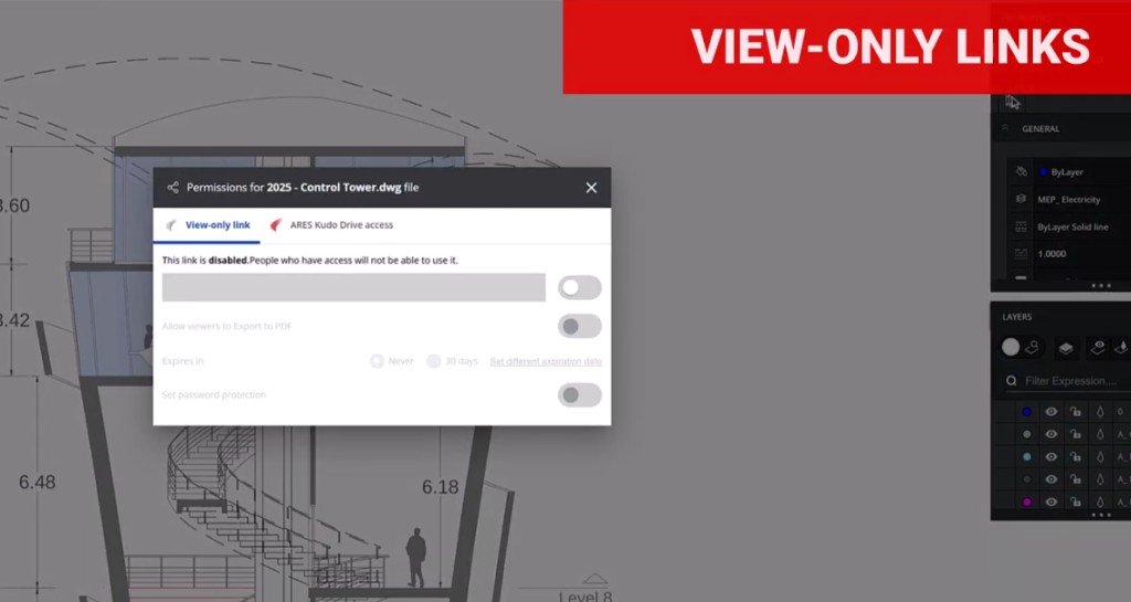
Learn how to share DWG-format CAD drawings easily and efficiently by using view-only links. Avoid the hassles of email attachments, prevent version confusion, and collaborate in real time.
Going into the new year, it’s time to take stock of what’s going well in your CAD workflows — and to discard outdated practices that are bogging you down. Making even a small upgrade in your daily routine can have a big impact.
Your file-sharing practices are a great place to start. Sharing information — both inside and outside your company — is fundamental to collaboration. But when it comes to efficiency and security, sharing methods are not all equal. If you’re still sending DWG files to collaborators via email, you’re wasting time, taking unnecessary security risks, and introducing confusion with multiple file versions. It’s time you learned about a better way to share: A URL that recipients can simply click on to view your file.
A view-only link is a modern way of sharing CAD content, allowing recipients to always see the latest, live-updated version of the file. While there may be times when you need to convert your DWG drawings to PDF format for sharing, PDFs can only capture a snapshot of the drawing at one particular moment in time; they’re not automatically updated as the drawing evolves. With view-only links, in contrast, any changes made to the file are reflected immediately, making it unnecessary to resend files.
In addition, with view-only links, you retain full control over the DWG file you’re sharing. You can protect it with a password, set an expiration date, and even revoke access to the file at any time.
Sharing information via a link is significantly more convenient than doing so via traditional email attachments. This modern process offers the following advantages:
Quick and easy sharing. You can share specific files, or entire folders, just by generating and sending a link. You don’t have to worry about the size or format restrictions of email attachments, even for large files such as drawings. This ease of use also reduces the risk of human errors, such as accidental email transmission of the file.
Access to the latest version — always. Once a shared link is issued, the recipient can always access the latest information at the link destination, because any changes made to the file are reflected in real time. This greatly reduces the hassle of exchanging and managing multiple versions of the same file.
Real-time collaboration. With link sharing utilizing cloud services, multiple people can view the file simultaneously, even while it is being edited — creating an environment for real-time collaboration and information sharing within a team.
Security ensured by access rights. Since access rights can be finely tuned for each file, using settings that restrict who can view or edit it, users can share information while maintaining the desired level of security.
A simple way to collect feedback. Even the link users who only have viewing rights can add feedback and validate the file, by using the intuitive commenting and markup tools. Collaborators’ comments and markups display feedback in context, so it’s easier to understand, yet they don’t affect the drawing itself.
In the ARES Trinity of CAD software — which comprises ARES Commander, ARES Kudo, and ARES Touch — the view-only link feature enables users to safely and efficiently view and provide feedback on shared CAD drawings. By generating a unique link from the sharing options and sending this link to the person you want to share with, you make it possible for that person to view the drawing in a web browser.
View-only links can be created in ARES Commander (the desktop version of ARES), ARES Touch (the mobile version), and ARES Kudo (the cloud version). Drawings can be shared with anyone via the link; the recipient does not need to have an ARES software license.
View-only links have substantial benefits for those sharing and receiving CAD files. Here, we’ll look at just a few of the possible scenarios where this feature can make a big difference.
Use Case #1: Accessing drawings while working from home or on a business trip
The view-only link is convenient when you want to check drawings while away from the office. Since it can be accessed from a browser, the device you’re using is irrelevant — you don’t need the desktop computer or workstation you normally use at work. Also, unlike traditional sharing with file attachments, you can view the drawing with just a click; there’s no need to download any software, or open anything other than a browser.
Notably, you can share a drawing with people who may not be CAD users — such as clients or sales staff — simply and easily. The view-only link allows the link creator to assign viewing permissions only, without editing rights. The link can be configured with an expiration date and/or password, ensuring confidentiality.
Use Case #2: Collaborating in real time with multiple people
ARES is rich in collaboration features for projects. The software prevents conflicting changes by allowing only one person to edit at a time. A mechanism is included where editing rights automatically transfer to the next user if the current editor is inactive for 25 minutes, preventing problems if a user forgets to log out when finished.
In projects where drawings are frequently updated, sharing via file attachments often results in multiple versions and can cause confusion. In contrast, the view-only link always displays the latest version of the drawing, making version management easy.
Furthermore, feedback on drawings can be given through written comments, photos, voice recordings, or stamps, allowing for real-time exchange of opinions.
Use Case #3: Improving sharing security with fine-grained access management
The view-only links feature in ARES allows users to share drawings while maintaining security. Access rights can be flexibly set for each user, giving each individual the ability to edit the drawing or only to view it, for example. Access history is also recorded, so it is clear who accessed the file — and when — at a glance.
ARES can connect to major cloud storage services such as OneDrive, Box, and Google Drive. Saving files to cloud storage provides robust security.
In summary, view-only links are a modern way to share DWG drawings with collaborators, whether they’re CAD users or not. When compared with email attachments, view-only links provide substantial improvements in security and convenience — and they’re very easy to use, for creators and recipients alike. Start your free ARES trial today and discover a secure, modern way to share CAD drawings with view-only links.
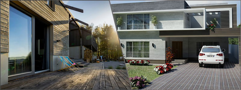
There have been minimal improvements when it comes to construction practices used and enforced in the industry. These techniques, which seem to be the standard since the Jurassic era, have produced houses and buildings that have been criticized as inefficient in terms of cost, design, and overall aesthetic. Many houses even fail to cater to the current market demand.
But of course, if you want to stay ahead of the curve and achieve success in the progressive residential construction industry, you need to think outside the box and explore more modern solutions. Catering to the ever-evolving market, the demand cannot be fulfilled by simply generating more and more houses. The solution should be as innovative and new as the continuously improving technology and practices. One key methodology gaining traction in today’s construction industry is DFMA or design for manufacturing and assembly services.
DFMA is a methodological approach that optimizes the design process to allow a more efficient and seamless assembly and manufacturing. It ultimately leads to standardization, which will give you and your company faster construction timelines and cost savings. This article will share with you how building design and construction companies can take advantage of DFMA to design affordable homes.
DFMA, or Design for Manufacturing and Assembly, is a framework focusing primarily on designing products that can be manufactured and assembled easily. This design process is not something that is new in the industry; it has been used since the 1980s to minimize the overall costs of computer hardware, consumer appliances, automobiles, and even airplanes.
These products are designed and crafted by DFM design professionals using individual components and parts that are aligned to be built and assembled in a factory setting. The buildings that will be worked on are considered products that can be split into several modules that can be built step by step and part by part. These modules which can consist of different parts and workings, are repeatable, interchangeable, and standardized.
Benefits of DFMA homes
Houses built using DFMA aim to lessen a large chunk of lifecycle costs, including build cost, construction and design time, carbon intensity, and household energy consumption while improving construction productivity.
Expected economic benefits of DFMA housing projects
It allows other registered providers and 3D designers to reproduce the business model in partnership with the rest of the group to achieve a multiplier effect.
It reduces labor requirements per house, improving the industry’s resilience to a labor shortage, an existing concern that might only worsen over time.
It creates new business opportunities for suppliers.
It cuts down regional construction costs and speeds up delivery time to meet the targeted deadlines.
It decreases the energy bills of homeowners.
Other social benefits
It creates a safer work environment for the production process compared to traditional onsite production.
It creates new skills and roles for future use.
It improves quality of life by creating a more comfortable living environment and disposable income.
It provides faster access to affordable or social housing.
Reasons why the modern construction industry moves towards DFMA
The ultimate outcome of 3D construction rendering services and design is to create reasonably priced buildings within an accepted timeframe. DFMA or prefabrication is a good example since it uses modular construction drawings and already manufactured construction drawings. Once combined, these techniques and modules simplify the manufacturing part by outsourcing different offsite components which will give you a balanced performance, quality, and a more acceptable cost.
In DFMA drawings and models, assembly and manufacturing are elegantly intertwined together to have a simple, efficient, and error-free construction. However, just like other combined processes, DFMA might present complications and challenges at one point. However, the perks of reducing materials, overheads, and labor costs offer the ultimate solution to achieving success with minimal wastage and higher profit margins.
During product assembly, DFMA follows a meticulous design review process. It identifies optimal part design of products as well as cost-effective and efficient production methods that cater to the requirements of the designers and the rest of the team members.
Entire units or parts of the building’s construction are crafted in a factory setting or an actual factory away from the construction site before being transported to be installed on the site. Prefabricated construction modeling and DFMA encourage seamless collaboration between project design and production, making the products more cost-effective and reliable.
Here are other reasons to take advantage of DFMA for designing affordable homes:
Ability to test
It’s possible to consider offsite solutions early on in the planning stage with the help of building information modeling experts or the BIM process. BIM aids in delivering prototype specifications to allow extensive testing. Models can also undergo virtual testing before companies invest finances in their actual prototypes.
Cost
Fewer parts are used in DFMA, which eliminates unique parts and cuts down the labor count for assembly. It also uses standard hardware and parts, reducing the need for assembly tools and thus further decreasing the costs involved. The DFMA process offsite is predictable and not prone to delays and material damage due to weather, helping save overall costs. It’s also possible to use the same parts interchangeably for product manufacturing, decreasing the number of parts and costs.
The application of total quality or operational management tools can help fulfill future volume needs. Projects involving repetitive structure elements, such as supermarkets, malls, colleges, schools, hospitals, and hotels, can also significantly benefit from DFMA, as it easily replicates elements in larger quantities after choosing the design.
Availability of resources
Construction in a different environment requires less onsite labor to relieve shortages in skills. Onsite resources are necessary only for the final installation of assembly instead of the design, manufacture, and complex assembly of parts and components.
Safety
Entire buildings or components can be reconfigured and transferred to different sites to ensure improved safety of future deconstruction of buildings. Prefabrication work in controlled factory settings is done following controlled and safe protocols for health and safety. The site also has more spaces and fewer external factors for various trades taking place within the same space.
DFM experts help optimize and simplify the manufacturing process, particularly through modules. The modules in the product design resulting from prefabrication can simplify testing, inspection, redesign, purchasing, assembly, service, maintenance, and the rest. Assembly is also simplified through self-locating and self-aligning parts, including molded keyways, chamfers, indentations, and projections. DFMA also reduces elements for interconnections.
The interconnected parts are flexible and can be used to connect two more parts. The harnesses guarantee unique connectors prevent misalignment. It also simplifies inventory and improves servicing and maintenance processes. Modules can make the redesign process more versatile to help with testing before the final assembly and allow the use of standard elements to cut down product variations.
DFMA also avoids multiple cleaning and solder steps. Prefabrication also simplifies the identification of problems and the assembly process’s operations. Self-contained and separate modules also require fewer tools with reduced disassembly and overall repair time. Using multifunctional parts also allows the execution of several constructions by just a single part, thus making the procedure less complex.
Site space
DFMA also offers huge benefits to sites with limited access, limited space, and complex logistics ,such as city center locations and airports. Even sites that don’t have house storage and those that can handle the delivery of semi-prepared or raw materials can also benefit from DFMA. Offsite prefabrication also results in less labor and material onsite, thus opening up more onsite space.
DFMA helps eliminate or reduce interfaces, which decreases assembly time. The use of standard assembly practices like self-aligning parts and vertical assembly cuts down assembly time as well. Products made through DFMA can also smoothly and quickly transition to the production stage. This reduces the time required for the product to travel from the conception phase to its ready-for-market phase.
Stack or vertical assembly also requires less reorientation of parts to speed up the process. Self-aligning parts like roller bearings, ball bearings, and washers don’t require additional reorientation or adjustment to save time. Remedial or snagging works also take less time. It also regulates and controls the reworking and sequencing of trades to cut down some of the more common onsite delays.
The manufacturing process can also be designed to pay close attention to the smooth flow of materials, reduced number of material moves, reduced brazing and welding, use of easy-to-control processes, separation of mechanized and manual operations, and simultaneous performance of similar operations.
How Cad Crowd can help
Needless to say, the use of DFMA for home building design and construction companies offers a long list of benefits. Ultimately, the best DFMA solution will only be possible with the help of experts. Contact Cad Crowd, and we will help you find the right experts for your DFMA projects!
MacKenzie Brown is the founder and CEO of Cad Crowd. With over 18 years of experience in launching and scaling platforms specializing in CAD services, product design, manufacturing, hardware, and software development, MacKenzie is a recognized authority in the engineering industry. Under his leadership, Cad Crowd serves esteemed clients like NASA, JPL, the U.S. Navy, and Fortune 500 companies, empowering innovators with access to high-quality design and engineering talent.
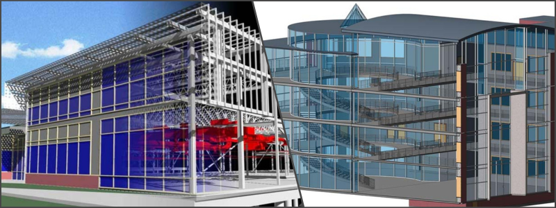
The term BIM, or building information modeling, crept into the construction world in the 1970s when CAD systems were developed. Initially, BIM was meant to serve as a library of 3D symbols, with BIM objects being the digital modeling of concrete blocks, windows, or air conditioning units. Data entered the picture instantaneously, making BIM a catalyst of property and information revolutionizing the modern construction industry.
Implementing BIM (building information modeling) offers many benefits to construction companies. However, it’s critical to use functional and quality BIM objects and employ architectural BIM modeling services for experts in the field. Construction companies, design offices, and architects have much to gain from these tools.
Bridge the gap between key players with quality BIM objects
BIM holds one promise: to facilitate cooperation among the players involved in a construction project in a more centralized way. Therefore, the first quality of BIM objects is to use a common language between the different participants of the project, specifically building engineers, builders, architects, and engineers.
Quality BIM objects also allow improved collaboration between various project participants. By accessing updated and accurate information, all parties in the joint project can work and function more efficiently. BIM object properties should be standardized based on formats compatible with each participant’s software to ensure that everyone can read them. This is the key challenge for the manufacturing companies and the condition for objects to be qualitative.
Defining BIM objects
Building information modeling, or BIM, is considered the future of the construction industry. BIM breaks down the silos that prevent collaborative engagement to enable a seamless flow of information among various construction stakeholders. The main goal of BIM is to make data accessible immediately to all stakeholders. BIM’s nature is similar to social media, where everyone can provide input, access data, and eliminate possible conflicts.
Building a construction-ready and information-rich BIM is more challenging than building a design model that looks pretty for client presentations. The adage GIGO or Garbage In, Garbage Out explains the philosophy of BIM quite well. It’s important to feed in precise data from various stakeholders to establish a useful model that depicts the actual conditions of the site. Thus, developing a BIM model using 3D modeling design services is an iterative and painstaking process.
As the building blocks of BIM models, BIM objects are intelligent and data-rich with geometry. BIM and the resulting BIM objects offer benefits in three key areas: planning, construction, and facility management. Aside from the product and visual data, BIM objects can also store functional data. It allows BIM objects to imitate the actual performance of the product. If any of the construction project stakeholders make changes to the BIM object, the change will reflect across the board right away.
The planning stage can benefit from BIM objects in several ways, including the following:
Detect and resolve clashes
Detecting clashes and their ensuing resolution will become easier when the subcontractors can envision details in lifelike models. For instance, in which locations do electrical fittings clash with plumbing fittings? Will the planned foundation clash with the current underground facilities? Having these actionable insights ahead of time will prevent the need to change designs much later. The quality of data also increases significantly when BIM objects are used.
Optimization and simulation
BIM objects help mimic real-life conditions in the model. For example, do you plan to design an energy-efficient building? Does the building insulation perform based on the requirements of the design? Are there any areas where energy loss may occur? Readily available BIM objects make it easier to test various products to identify the best one.
Visual communication
Better visual communication is no doubt the most obvious advantage of making use of BIM modeling experts. Construction managers can share BIM models with the stakeholders and the owners alike. Virtual mock-ups or lifelike visualization give clients and stakeholders better insights into proposed sequencing. The ability to easily convey data makes BIM superior to 2D blueprints and plans. Complex constructions and slopes that are difficult to visualize in 2D alone can be easily understood and visualized in 3D BIM models. In addition, when powerful and emerging technologies such as drone mapping are used in conjunction with BIM, the result is an accurate and lifelike model.
Implementing well-thought-out processes and systems is critical to building accurate BIM models. Without these systems, correct simulation of the site’s conditions is impossible. For example, bar codes should be attached to construction and equipment components for tracking and cataloging. The site manager should scan equipment once it arrives and during its installation.
After the tracking system is in place, other details, such as the date of shipping and operation manuals, can also be entered into the database. Building accurate BIM models also calls for continuous and intensive subcontractor training. The project manager should set uniform standards across the board. For example, one common problem on construction sites is that several subcontractors might use different points of reference. This kind of discrepancy can be avoided right from the beginning with the help of BIM and 3D architectural visualization services.
Coordination during construction
Tying the construction schedule to the model has several benefits, such as allowing the creation of 4D movie-like simulations. A visual view of the sequencing allows subcontractors to understand how their work will fit into the construction schedule. For example, if you need to explain the scope of construction and work sequencing to the glazing subcontractor, BIM allows you to easily create movie-like simulations where different colors depict different sub-phases of the glazing job.
Suppose you’re modeling a building’s structural details. After these details are modeled, you may be given details of the overlaying elements, such as connectors and gasket plates, from the fabricator. Once these are built into the BIM model, the contractor will better understand what goes where. With the help of BIM objects specified by the manufacturer, the 3D product modeling designers can acquire helpful inputs from the manufacturer to ensure a more collaborative design phase.
Prefabrication
The use of BIM models improves safety in construction sites. Construction managers can accurately estimate dimensions and quantities and can turn to prefabrication to a greater extent. Since more work is done in controlled and safe confines of warehouses, only a limited number of people are required on-site, resulting in safer operations. The use of manufacturer-specific BIM objects gives the assurance that the prefab structure will have a perfect fit.
Construction managers can save more time if BIM models are used to carry out their quantity takeoffs. If the 3D architectural modeling professionals utilize BIM, it results in more accurate estimates. For example, constructing a building with different elevations requires hundreds of distinct columns with varied dimensions—the usual, although inaccurate, practice is to average out the columns’ areas. But thanks to BIM, it’s possible to estimate the quantity of every column and reach a total. It would lead to a more accurate estimate of the cost and quantity.
The role of BIM objects in facility management
Aside from the planning stage and actual construction phase, BIM also drives cost savings and efficiencies in facilities management. The initial end-use of BIM models is in terms of maintenance, emergency, and preventative. BIM allows linking resources such as operating manuals, project images, and training videos to every component. If the facilities manager encounters a breakdown, it only takes a click of ginger to access the necessary data. Better control over renovations and retrofits is another great reason to incorporate BIM into the construction workflow.
For example, if a chemical plant wants to upgrade the boiler capacity from 25T to 5T, it must strengthen the foundation and raise the elevation. The execution of the project would be more straightforward if BIM were used to build the chemical plant. Estimating quantities and assigning a timeline and costs to the whole project is also easier with the help of BIM objects. Using functional and quality BIM objects gives construction companies and project lifecycles the chance to improve the efficiency, profitability, and quality of their construction projects by making the most out of the benefits and power of these unique digital tools.
How Cad Crowd can help
Cad Crowd is more than happy to assist you in finding the best BIM modeling services and BIM modeling experts who can help your company transform construction projects and take them to a whole new level!
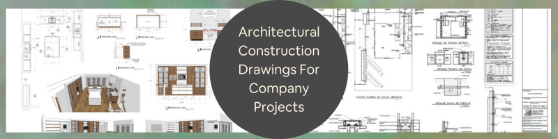
Today’s post covers architectural construction drawings and how companies apply them in their projects. The term “construction” evokes vivid images, from hard-hat-clad workers to the hustle and bustle of material transfer between various points. But as far as construction is concerned, you might think of construction drawings or plans. For novice eyes, these drawings and plans might look completely alien, incomprehensible, and impossible to understand. However, if you ask any freelance construction drawings and CAD drafting and design professionals, they will tell you that a construction drawing is always the first step in any construction process.
Freelance architectural construction drawings are among the most fundamental things you need before you begin the construction of your structure. These construction drawings are used in architectural and construction activities and projects for various applications and reasons. This post will give you a walkthrough of the different types of architectural construction drawings and how companies use them.
Architectural construction drawings are graphical representations of what will be built and how it will be laid out, together with details of dimensions, framework, and components. A specific construction drawing created by a construction drawing professional highlights the details for each aspect and stage of construction projects. Construction drawings that include each subtype help various workforce groups tasked to do or oversee the tasks involved in a construction project.
The making of architectural construction drawings
Architectural construction drawings are rarely hand-drawn. They are now mostly sketched and rendered with the help of computer-aided draftings like CAD or computer-aided design software and 3D construction rendering software. BIM, or building information modeling software, has revolutionized the accessibility of creating detailed visualizations and renders for VCMs (virtual construction models). Additionally, integrating architectural BIM modeling services further enhances the precision and efficiency of the construction planning process. Let’s now look at the most common architectural construction drawings often used in today’s construction industry.
Architectural drawings are the drawing works used in construction drawings. Their primary purpose is to depict the layout, depth, and dimensions of the actual building before the start of its construction. With the aid of architectural drawing firms, these architectural drawings act as blueprint construction and are drawn to scale to make it easier for engineers to envision the project.
Architectural drawings and architectural drafts also have different types often used in construction projects, and these are the following:
Elevation Drawings
Elevation drawings are architectural drawings that provide an aesthetic overview of the different building components, such as doorframes, windows, and columns. It also allows a better understanding of the internal markings, relative surface, and relative height of the various components to one another.
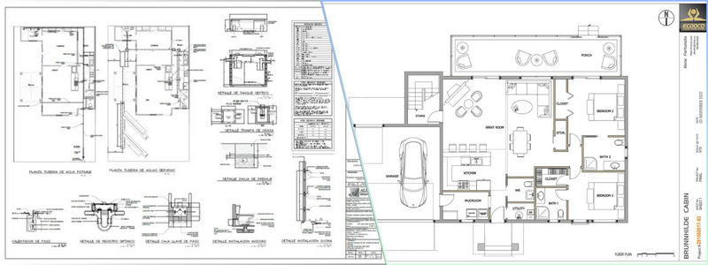
Floor plans are the in-depth renderings of room layouts for every floor. 2D drawings and floor plan services describe the orientation of components and rooms to each other. While floor plans might or might not be used in non-commercial or commercial building projects, it is still necessarily made as an integral part of the entire drawing work.
Foundation plan
Often mistaken for basement or ground floor plans, foundation plans are the drawing works that render any of the floors of a building under construction. Foundation plans help envision the height, configuration, shape, size, and dimensions of rooms, landings, or stairs with each other.
Sectional drawings
Sectional drawings depict the entire framework or a part of it in a sliced form. These drawings help us understand the specific measurements of the different components of the building with each other, the hollowness, height, and depth of these components, as well as the materials used to construct them.
A block plan is a drawing that presents the site’s layout or the surrounding nearby buildings, all drawn to scale and laid out on a map. Block plans offer a firsthand idea of the boundaries, roads, and other similar details, all of which are essential to understanding the location of your construction site. An experienced architectural detailing professional can help. These architectural construction drawings can help people involved with your construction project or plan request understand better where or what you are proposing and assist you with this. A block plan about the suggested scales and ordinance survey maps is also developed.
Electrical drafting or drawings
Many commercial or residential construction drawings also call for a functional outline of the specific number of power outlets, fan fixtures, and light fixtures. Electrical drafting & design experts can develop electrical drawings that indicate the wiring pattern and the details regarding the electrical load each can carry. Some of the most common details that you can find in electrical drawings include:
One of the most critical aspects of construction projects that companies should never overlook is ensuring that environmental management and guidelines are strictly followed. The goal is to reduce the construction project’s potential environmental damage and possible adverse effects. Environmental plans include several measures, such as:
Chemical disposal mechanisms
Management of sedimentation and erosion
Measures to handle emergencies and accidents like fire
Outlining measures for environmental guideline compliance
Finishing drawings
After setting up the entire architectural and structural framework, the finishing drawings include the finer and more comprehensive building plans. These are necessary for the functional and aesthetic value of a building. Construction drawings often include details of the following:
Safety design has become more critical than ever in modern-day construction systems. Fire sprinkler drawing services are included in a building’s blueprint drawings that designate points or spots for fire escapes, fire hoses, sandbags, water outlets, and other equipment for fire safety, as mandated by the regulatory body that oversees the project.
HVAC design services and drawings
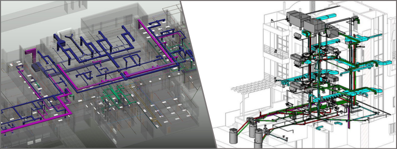
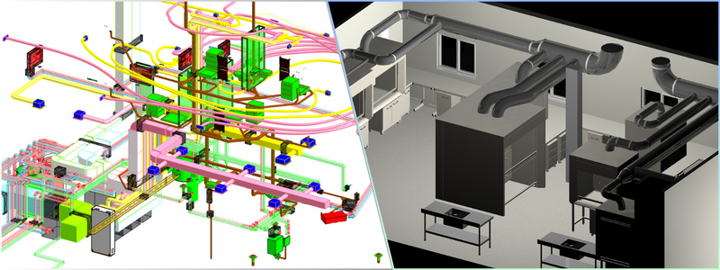
HVAC design services and drawings, also called mechanical construction drawings, offer a design framework and details for ventilation and heating systems in the building. Air conditioning vents, central cooling or heating, ventilators, and others are all indicated based on the need and the site of the building plans. The builders use the HVAC design drawings in the process accordingly.
Similar to electrical layouts, plumbing is yet another part of any commercial or residential architectural construction drawing that specifies the points where plumbing parts and components will be set up. Spots and spaces are allotted here accordingly for additional sanitary ware and pipe fixtures that will be added after the completion of the structural component. Plumbing drawings often include:
Outlet points such as tanks, taps, and sinks
Pipes, including water pipes, internal pipes, and drainage pipes
Location and position of outlets and pipes
Pipe materials
Production drawings
Production drawings are architectural construction drawings that present functional data to the onsite engineers and workers. These drawings describe the assembly of different parts, the materials, the dimensions, the necessary tools, and other details required throughout the process. Production drawing designers may also include an infographic or additional information on how to meet the set requirements.
Structural design firms create structural drawings that are used as civil engineering drawings. These drawings come in handy to better understand a building framework and its physical nitty-gritty. These drawings guide a structural design that the onsite engineers and workers can refer to.
Structural design drawings have several common types, including:
Beam layouts
Beam layouts include all beam-like structures, like those supporting the windows and roof, and beams meant for strengthening. These are designed for every floor, covering the material, height, length, and others.
Column layouts
Column layouts are structural drawings that indicate how columns are laid out. This will make it easier for the contractors to plan the building layout and begin the process by identifying the position of the columns and the distance between them across the floor.
Excavation drawings
A civil engineering design firm can draft civil engineering drawings that describe the positions and dimensions for the excavation process before the actual building work. Excavation drawings cover details such as shafts, tunneling, grid plans, removal of soil, and others necessary to begin the groundwork.
The general note is the overview of all the procedures, abbreviations, codes, and others required to provide a comprehensive guide for working on the construction site. It includes details for the rest of the structural drawings, construction types and lengths of every component, and concrete mix, to mention a few.
Roof slab layouts
These structural drawings describe the exact dimensions of every slab required for slants or roofs. Roof slab layouts can be designed using AutoCAD software, which calls for data and precision. Previously, these architectural construction drawings were made manually. However, with the rise of new technologies, CAD software programs have made things more accessible.
How Cad Crowd can assist
Explore architectural construction drawings with Cad Crowd to understand their types and importance for businesses. Our blog post explains various types of architectural construction drawings and their practical applications, helping you use them effectively in your projects.
Contact Cad Crowd for expert guidance to simplify your architectural construction drawings and design journey. Request a free quote now!