
Contributed by Autodesk Community member Arshdeep Singh
One of AutoCAD’s greatest features is its ability to be customized to your specific needs. With a little bit of customization, you can set up your own tabs and commands in the ribbon. Adding your most frequently used tools under a single tab not only saves time but also streamlines your design workflow. In addition, you can organize the commands in a logical grouping to help reduce time spent navigating through different menus.
You don’t need any programming experience. The Custom User Interface (CUI) makes it very easy to build menus and preview the changes. This blog post explains how to get started with AutoCAD ribbon customization, helping you tailor the platform to your specific needs. At the end, you will successfully be able to modify the AutoCAD ribbon.
AutoCAD Ribbon Customization: Understanding the Basics
Before we move any further, it’s important to understand the terms ribbon, tabs, and panels.
Ribbon: The ribbon is the horizontal interface at the top of AutoCAD which contains all the tools. It organizes and displays commands in logical grouping using tabs and panels for easy access.
Tabs: Tabs are part of the ribbon and categorize related groups of commands. For example, Home, Insert, Annotate, etc.
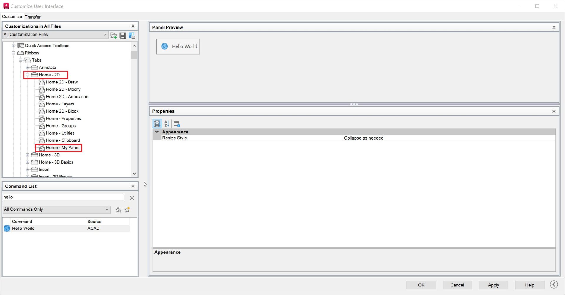
Panels: Panels are subdivisions within tabs that group related commands further. For example, the Block Panel under Home Tab contains tools related to blocks like Insert, Detect, Create, Edit, etc.

Working with the Customize User Interface Editor
To get started, you will need to open the Customize User Interface (CUI) Editor, which can be accessed under the Manage Tab – Customization Panel. Alternatively, you can also type CUI on the command line to open the Customize User Interface (CUI) Editor.

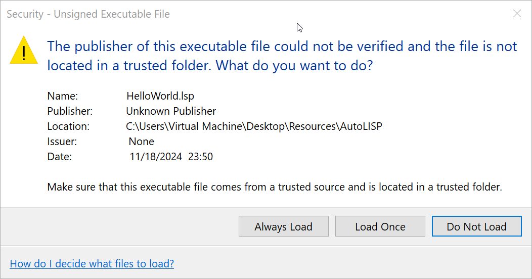
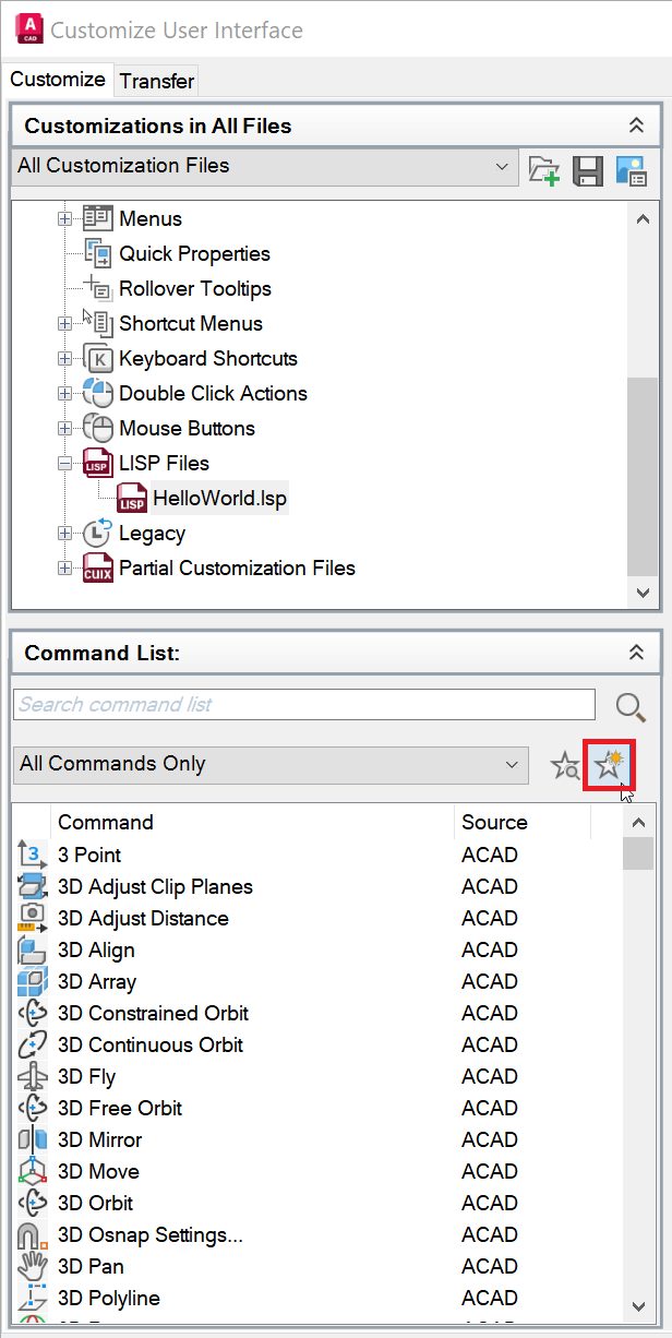
A cuix file stores all the interface customizations like the menus, ribbon tabs, and workspaces. It controls how the commands are organized and displayed on the Ribbon Tab. In addition, you can also add custom commands, keyboards shortcuts, LISP files, and change command images as well.
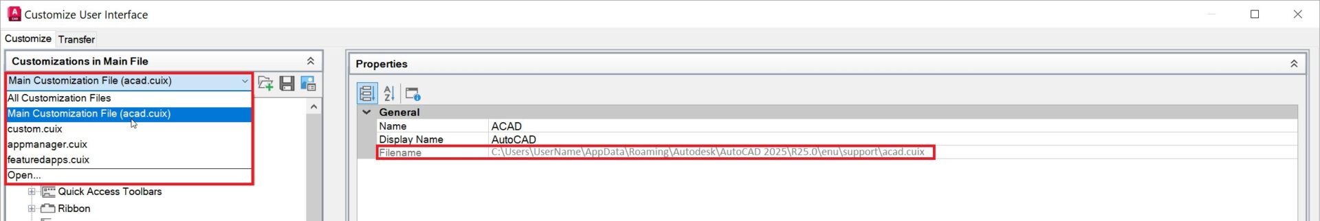
Once you open the CUI, All the customization files loaded into your AutoCAD will be listed under Customizations in Main File. The acad.cuix is the default customization file that is used by AutoCAD.
It’s always a good idea to backup the current customization file before making any changes. The customization file path is listed in the Properties Tab under General and Filename. Browse to the folder and make copy the customization file/s to a backup folder of your choice.
In this tutorial, we will add three very helpful commands to the Home Tab:
1. SAVEALL – This command saves all open drawings in your current AutoCAD session.
2. CLOSEALL – This command closes all open drawings, including the one currently displayed.
3. CLOSEALLOTHER – This command closes all drawings except the active one.
These commands are a part of the Express tools library which are provided with AutoCAD 2025 default installation. Enter EXPRESSTOOLS at command line to activate the Express Tools tab.
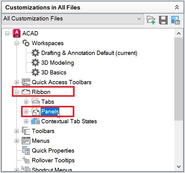
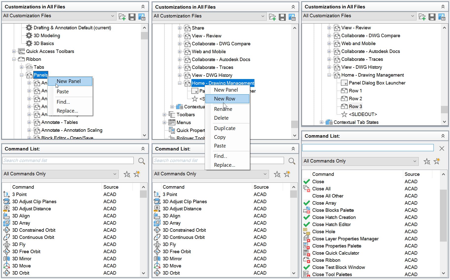
1. Launch the Customize User Interface (CUI) Editor.
2. In the left panel, expand the Ribbon Tab and the expand the Panels Tab.
3. Add a new panel and three rows. Give the panel a meaningful name, such as “Home – Drawing Management.”
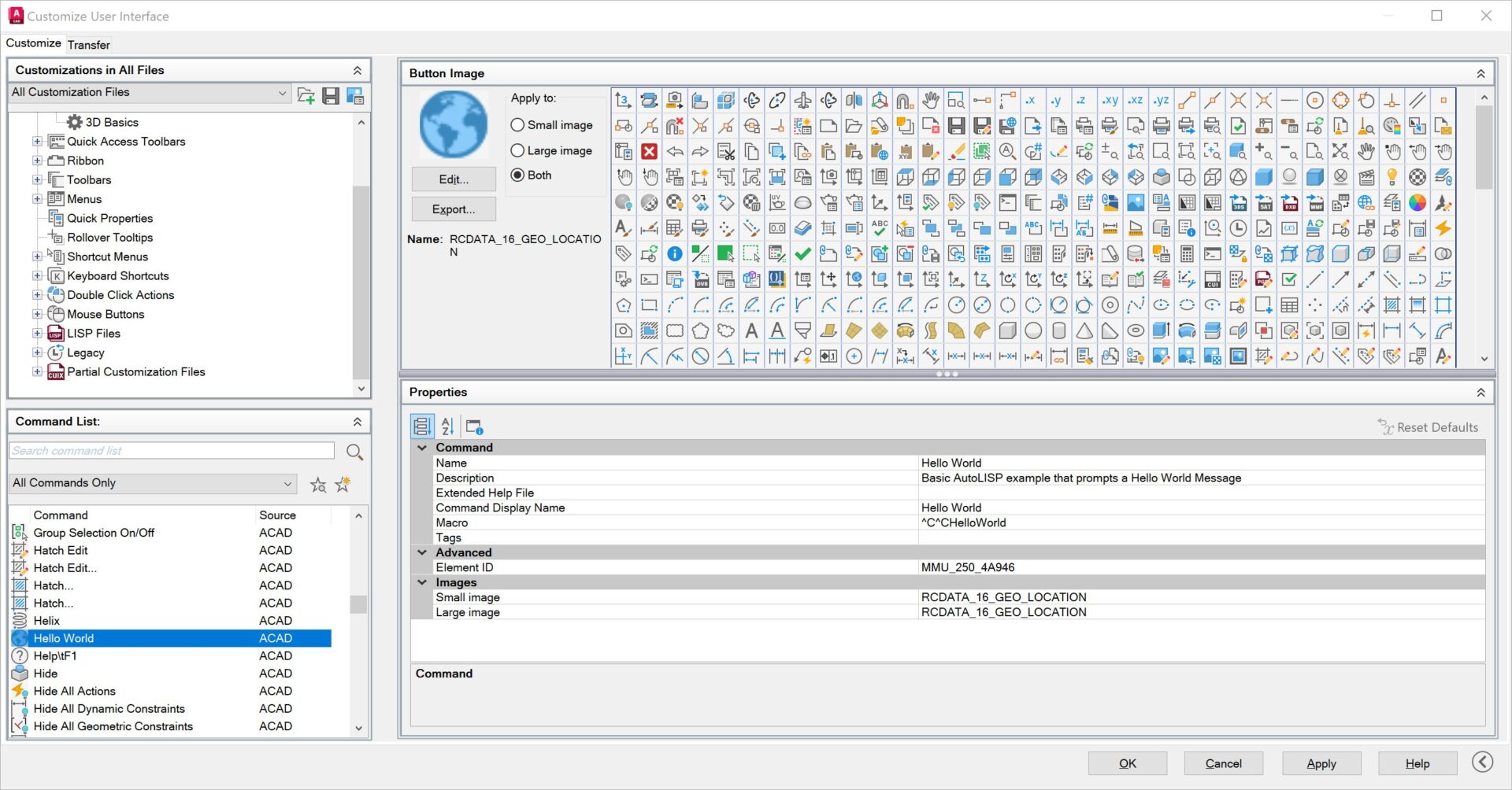
4. Add commands to the rows. Simply search the command you want to add in the command List section and drag and drop it to the Row under the new panel we just created.
Pro Tip: Not all the commands have icons assigned to them by default. You can simply add the icons by clicking on one of the button images while the command is elected under Command List. You can also add meaningful descriptions under the Description field which will display when your hover over the command.
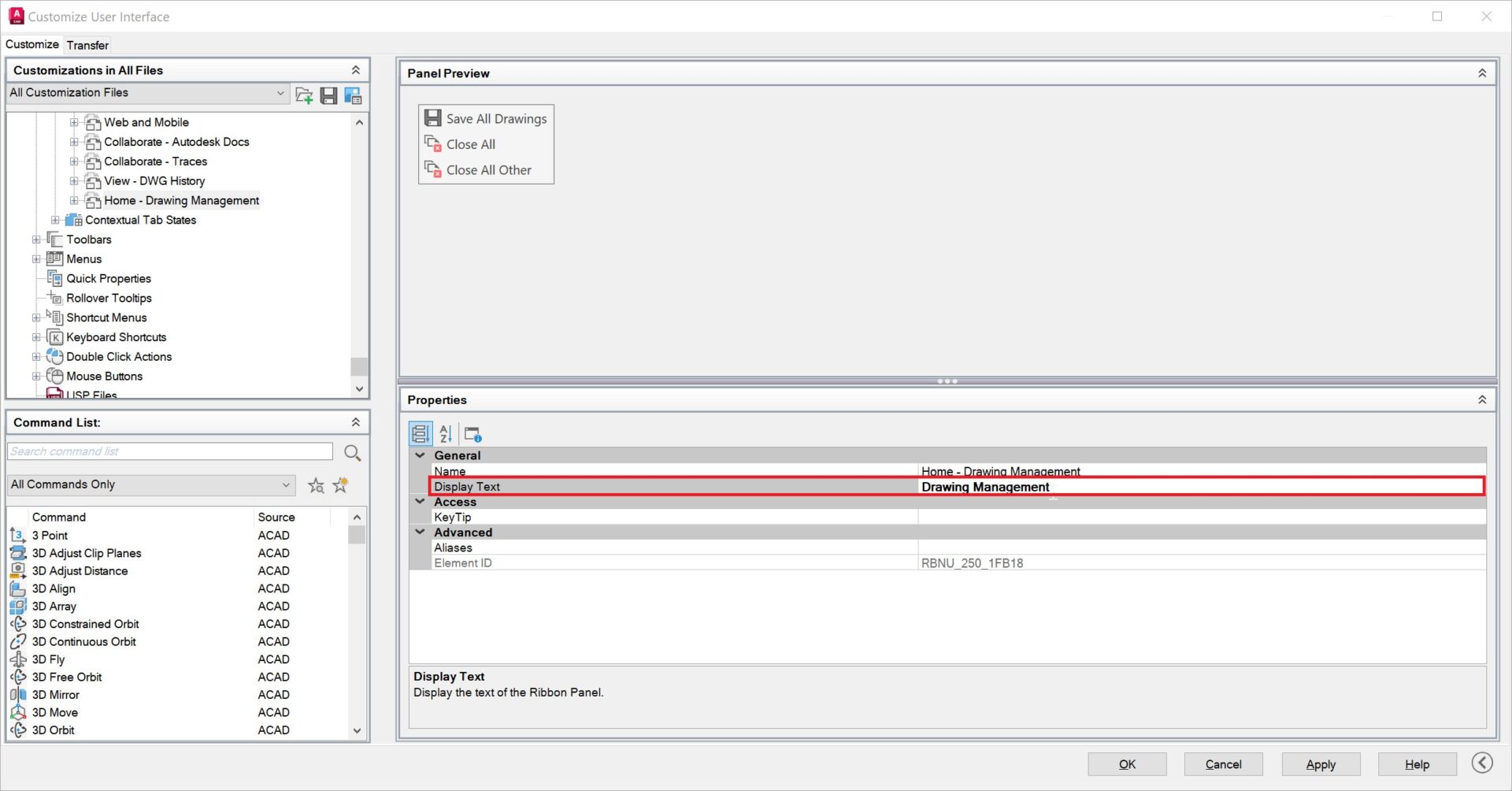
5. Set the Button style to SmallWithText for all commands. Panel Preview window will update the preview on how it would look on the Ribbon.

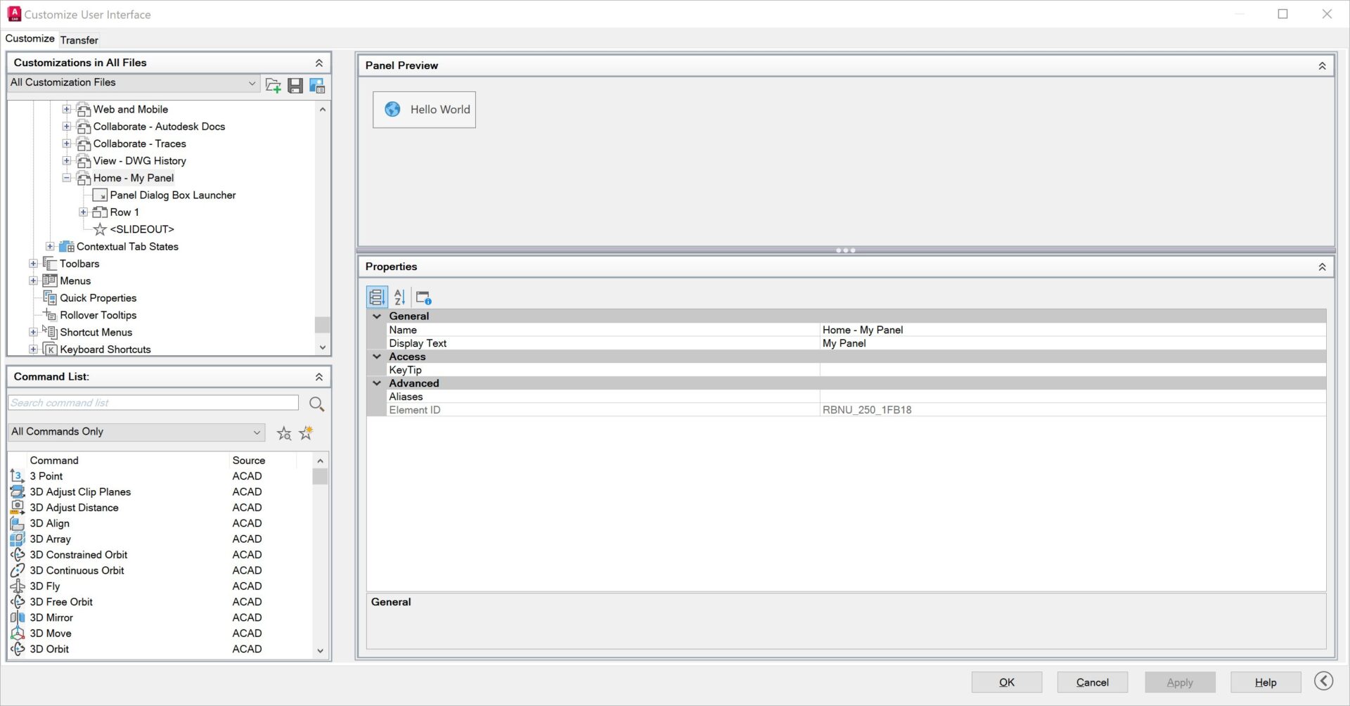
6. Select the “Home – Drawing Management” panel and give it a meaningful display text like Drawing Management.
7. Drag and drop or copy the new panel “Home – Drawing Management” to the bottom of the Home-2D Tab under Ribbon.

8. Press Apply and OK. Just like that, the new commands are added to the ribbon and are ready to be used.
Whether you are adding commands like “SAVEALL,” “CLOSEALL,” and “CLOSEALLOTHER” as we just covered in this blog or your most frequently used tools, customizing the ribbon can make your AutoCAD experience more tailored and productive.
Learn More
Enjoyed this article? Then check out the Autodesk Community for even more great content from talented users across Design and Make industries.